
Electronic-bird-chirper
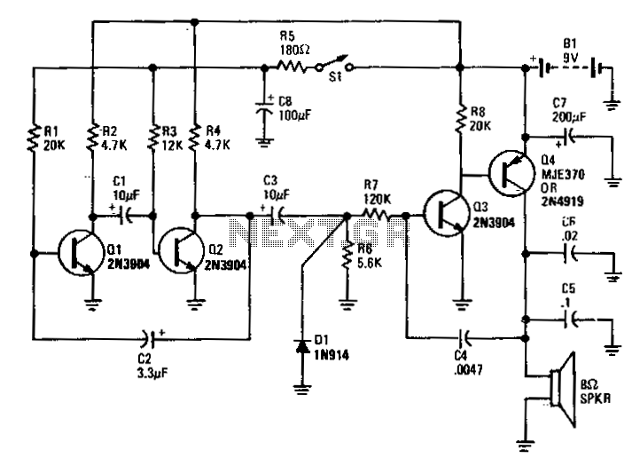
Transistors Q1 and Q2 form the two halves of a free-running multivibrator, with the frequency determined by the voltage across capacitor C8. This capacitor is charged and discharged by the operation of switch S1. Transistors Q3 and Q4 constitute a voltage-controlled oscillator (VFO). The output from the free-running multivibrator frequency modulates the Q3/Q4 oscillator, producing a chirping bird sound. The rate of chirps per second is dictated by the frequency of the Q1/Q2 multivibrator, which is variable. Additionally, the pitch of the chirps is influenced by capacitors C5 and C6.
The circuit described utilizes a free-running multivibrator configuration formed by transistors Q1 and Q2, which operates in an astable mode. In this configuration, the transistors alternately turn on and off, creating a square wave output. The frequency of oscillation is primarily determined by the charging and discharging cycle of capacitor C8, which is influenced by the closing and opening of switch S1. When switch S1 is closed, capacitor C8 begins to charge, and when it opens, the capacitor discharges, thus affecting the timing intervals and the resulting frequency of the multivibrator.
The output of this multivibrator serves as a modulation signal for the VFO created by transistors Q3 and Q4. This modulation introduces frequency variations to the output signal of the VFO, which is responsible for generating the chirping sound characteristic of birds. The modulation depth and frequency of the chirps can be adjusted by varying the control parameters of the multivibrator.
Furthermore, the pitch of the generated chirps is controlled by capacitors C5 and C6, which are likely part of the timing network or filtering stage in the circuit. These capacitors influence the frequency response and the harmonic content of the oscillation, thus affecting the perceived pitch of the chirping sound. Adjustments to the values of C5 and C6 can lead to variations in the sound produced, allowing for a range of chirp pitches that can mimic different bird species or create unique sound effects.
Overall, this circuit exemplifies the use of transistors in sound synthesis, utilizing basic principles of oscillation and modulation to create an auditory output that is both dynamic and variable.Transistors Ql and Q2 form the two halves of a free-running multivibrator whose frequency is determined by the voltage across C8. That capacitor is charged and discharged by closing and openingBwitch Sl. Transistors Q3 and Q4 make up a VFO. The output of the free-running multivibrator frequency modulates the Q3/Q4 oscillator, causing the chirping bird sound.
The number of chirps per second is determined by the frequency of the Ql/Q2 multivibrator, which also varies. The pitch of the chirps is determined by C5 and C6. 🔗 External reference