
Electronic Dice Circuit
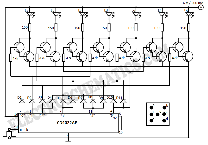
The electronic dice circuit utilizes a combination of integrated circuits and discrete components to simulate the rolling of a die. The primary component, IC 4022, is a binary counter that counts up to a predetermined value, in this case, six, corresponding to the faces of a standard die.
When the circuit is powered on, a push-button switch initiates the counting process. Each time the button is pressed, the counter increments its value. The output of the IC 4022 is connected to a series of LEDs, each representing one of the six faces of the die. The LEDs are configured such that only one LED is illuminated at a time, indicating the current value of the counter.
To ensure that the display is visually appealing and easy to read, the LEDs are typically arranged in a pattern that mimics the layout of a traditional die. For instance, the LED representing the number one is placed in the center, while the others are positioned to reflect their respective values.
In addition to the IC 4022, the circuit may include resistors to limit the current through the LEDs, ensuring they operate within safe limits and prolonging their lifespan. A capacitor may also be included to stabilize the power supply and prevent fluctuations that could affect the counting accuracy.
This electronic dice circuit serves as an excellent project for both educational and recreational purposes, demonstrating fundamental principles of digital electronics and circuit design. It can be further enhanced by adding features such as sound effects or a more complex random number generation algorithm to improve the randomness of the results.With this electronic dice the result is displayed with LEDs that are placed so every dice face is shown. In the circuit diagram, IC 4022 is used to count t.. 🔗 External reference
Related Circuits
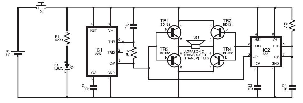
This ultrasonic sensor circuit consists of a set of ultrasonic receivers and transmitters that operate at the same frequency. When an object moves within the covered area, the circuit's balance is disturbed, triggering the alarm. The ultrasonic circuit is...
.png)
This document describes a simple engineering project circuit for a mobile cell phone detector (sniffer). This compact mobile communication detector can sense the presence of a mobile device, making it suitable for preventing mobile phone usage in private spaces,...
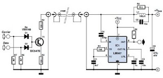
This circuit was designed to transmit commands over an LNB coaxial cable. An LNB (Low-Noise Block downconverter) is commonly used for satellite TV reception and is positioned at the focal point of a satellite dish. The circuit generates a...
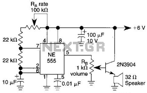
Ra sets the rate while RH sets the volume of clocks in the speaker. The 555 is configured as a low frequency oscillator. The circuit is powered by a 6 V battery. The circuit utilizes a 555 timer IC configured...
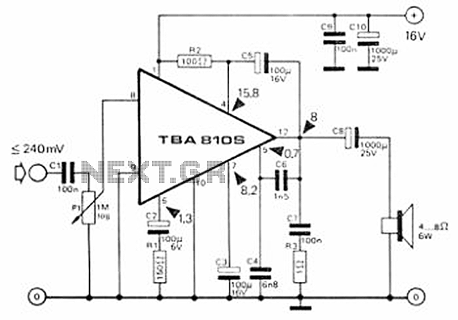
This circuit is a 7 Watt audio amplifier that is simple and easy to construct. It utilizes the TBA810 as the primary component, supported by a few passive components. The amplifier operates effectively, and the necessary kits and components...
The AM transmitter circuit consists of an audio amplifier and an RF oscillator. The oscillator is constructed around transistor Q1 and its associated components. The tank circuit, which includes inductor L1 and variable capacitor VC1, is tunable from approximately...
Warning: include(partials/cookie-banner.php): Failed to open stream: Permission denied in /var/www/html/nextgr/view-circuit.php on line 713
Warning: include(): Failed opening 'partials/cookie-banner.php' for inclusion (include_path='.:/usr/share/php') in /var/www/html/nextgr/view-circuit.php on line 713