
Electronic Doorbell with Counter
The circuit design is centered around the Holtek HT-2811 sound chip, which is responsible for generating the doorbell chime sound. This chip is programmed to produce a specific audio output that mimics the traditional ding-dong sound. The incorporation of the CMOS 4026 counter allows for a visual representation of visitor counts through a seven-segment display, which is essential for monitoring the number of times the doorbell has been pressed.
The circuit operates within a specified voltage range, ensuring that both the sound chip and the counter IC function efficiently while consuming minimal power during standby. The inclusion of a reset switch facilitates easy resetting of the visitor count, enhancing user control over the device. The common cathode seven-segment display is preferred for its simplicity in interfacing with the CMOS 4026, allowing for straightforward wiring and control.
Power management is a critical aspect of this design. A switch is implemented to enable or disable the display, contributing to reduced power consumption when the visual output is not needed. The count information is preserved in memory even when the display is turned off, ensuring that user data is not lost.
The chime's envelope, which determines the tonal quality and duration of the sound produced, is adjustable through the selection of resistor and capacitor values. This flexibility allows for customization based on user preference or specific application requirements. The debouncing circuit, created by the resistor-capacitor network, is essential for ensuring accurate counting by preventing multiple counts from a single press of the doorbell switch.
For applications requiring a higher visitor count, the circuit can be expanded by cascading two CMOS 4026 ICs. This setup allows for the tracking of up to 99 visitors, with the first IC handling the units and the second IC managing the tens. The connection between the two ICs is crucial for maintaining accurate counting across both displays, ensuring that the system remains reliable and effective in monitoring visitor activity.This circuit uses a synthesized sound chip from Holtek, the HT-2811. This reproduces the sound of a "ding-dong" chiming doorbell. Additionally, the circuit includes a CMOS 4026 counter display driver IC to count your visitors. The Holtek HT-2811 is available from Maplin electronics in the UK, order code BH69A. The operating voltage must remain wit hin 2. 4 to 3. 3 Vdc and standby current is minimal. The reset switch zeroes the count, and the 7 segment display is a common cathode type. To save power consumption the display can be enabled or disabled with a switch as shown in the above diagram. The count will still be held in memory. The IC pin out for the 4026 is shown in pin order below: The envelope of the chime is set by the 220k, 330k, 3u3 and 4u7 resistors and capacitors.
These values are the manufactures default values, but may be adjusted to alter the length and delay of the chime. The combination of the 2k2, 22k and 47u resistor capacitor network has a double function. It provides a debouncing circuit for the bell press and at the same time has a sufficiently long time constant.
This ensures that anyone rapidly pressing the doorbell switch, only advances the count once. The 47u capacitor may be increased in size, if needed. The count may be expanded for up to 99 visits by cascading two CMOS 4026 IC`s and using an additional 7 segment display. This is achieved by wiring pin 5 ( the 10`s output ) of the first CMOS4026 to pin 1 (the clock input) of the second IC.
🔗 External reference
Related Circuits
This project is not to introduce Tic Tac Toe. Everyone knows this game. It is to introduce two features: bi-coloured LEDs, microcontrollers, and the skill of writing an ALGORITHM. You can use the project to learn the skills of...
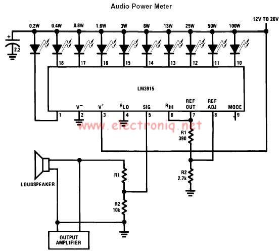
The LM3915 monolithic integrated circuit can be used to design a simple audio power level meter that senses analog voltage levels and drives ten LEDs, LCDs, or vacuum fluorescent displays, providing a logarithmic 3 dB/step analog display. One pin...
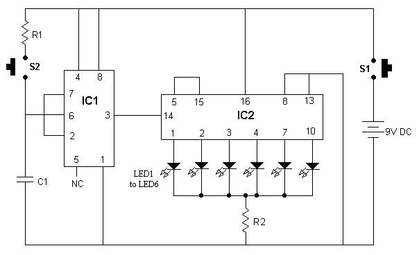
It is advisable to place this circuit in a box and label each LED with numbers 1 to 6. When switch S1 is pressed momentarily, one of the six LEDs will illuminate, and the number associated with the glowing...
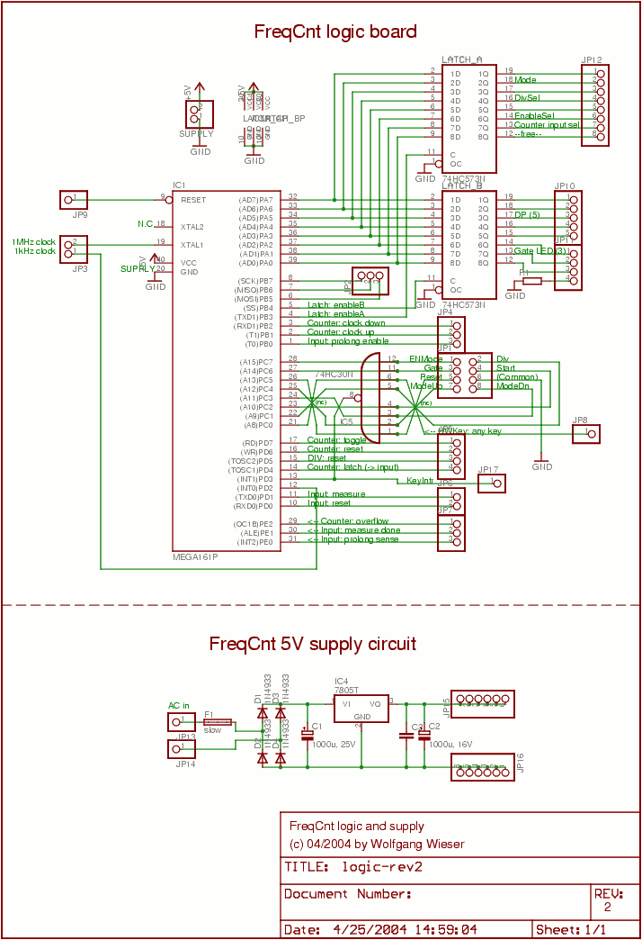
The lower schematic represents a standard bidirectional rectifier along with capacitors and a 7805 voltage regulator, which provides a stable 5V source to power the electronic components of the frequency counter. A fuse is included for security purposes. The...

This circuit is designed as a countdown timer utilizing a countdown calculation. It employs the 555 integrated circuit (IC) as the primary control element. The 555 IC functions as a counter and a transistor switch to activate a relay...
Doorbell for the Deaf. Circuit: Andy Collinson Email: [email protected]. This circuit provides a delayed visual indication when a doorbell switch is activated. The doorbell circuit designed for the deaf serves as a crucial tool for providing visual alerts in response...
Warning: include(partials/cookie-banner.php): Failed to open stream: Permission denied in /var/www/html/nextgr/view-circuit.php on line 713
Warning: include(): Failed opening 'partials/cookie-banner.php' for inclusion (include_path='.:/usr/share/php') in /var/www/html/nextgr/view-circuit.php on line 713