Electronic Ear for Lego RCX Module

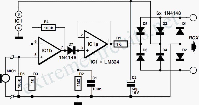
One interface that is missing in the Lego MindStorms system is an electronic ear. This does not imply that the RCX should respond to spoken commands, which would require extensive electronics and software. Instead, it would be beneficial if it could respond to basic sounds or sound levels. The circuit presented here allows the RCX to sense different sound levels. The sound is picked up by a crystal microphone, an inexpensive component readily available in electronics shops. The signal from the microphone is converted into a variable quasi-resistance value. The RCX can then use this value to determine if a particular sound level has been exceeded. If the trigger threshold is set correctly, the RCX will react to a previously set sound level. The RCX input must be configured as a light sensor input for this function. The operation of the circuit is straightforward. IC1, configured as a non-inverting amplifier, amplifies the microphone signal by a factor of 100. The output signal from the op-amp is rectified by D1 and smoothed by C1. Resistor R2 allows the capacitor to discharge. The resulting DC voltage drives IC2, which acts as a buffer. The output of this op-amp is connected to the sensor input of the RCX via a 1-kΩ resistor (R1). Similar to the analogue input adapter described elsewhere, the RCX perceives a variable resistance value at the sensor input, converting this into a measurement value ranging from 0 to 100. In the idle state, when no sound is detected, the measurement value lies between 90 and 100. As the sensed sound increases, the measurement value decreases. The light-sensor routine of the Lego software can be employed to set responses to various sound levels. With a threshold value of approximately 85, a level below 85 will be interpreted as a sound signal, while a level above 85 will be interpreted as silence. The circuit can detect sounds such as hand claps near the sensor. Additionally, by using these observations to increment a counter, it is possible to measure the number of sound pulses within a defined interval and subsequently execute an action based on the result.
The electronic ear circuit for the Lego MindStorms system is designed to enhance interaction by enabling sound detection capabilities. The core component, a crystal microphone, is sensitive to sound vibrations and converts them into an electrical signal. This signal is then processed through a series of components to provide a usable input for the RCX controller.
The first stage of processing involves amplification. The operational amplifier (IC1) is configured as a non-inverting amplifier, which increases the microphone's output signal by a factor of 100, ensuring that even faint sounds can be detected. The amplified signal is then rectified by diode D1, which allows only the positive half-cycles of the AC signal to pass through, effectively converting it into a pulsating DC signal. Capacitor C1 smooths this pulsating DC to provide a stable voltage level that corresponds to the intensity of the sound detected.
Resistor R2 plays a crucial role in controlling the discharge rate of C1, ensuring that the voltage does not drop too quickly and that the RCX can accurately read the sound levels over time. The buffered output from IC2 ensures that the signal sent to the RCX is clean and free from noise, facilitating accurate readings.
The connection to the RCX's sensor input is made through a 1-kΩ resistor (R1), which allows the RCX to interpret the varying voltage levels as changes in resistance. This setup transforms sound levels into a quantifiable measurement, enabling the RCX to react accordingly based on pre-set thresholds.
The operational logic of the circuit allows for dynamic interaction with the environment. By utilizing the Lego software's light-sensor routine, users can program the RCX to perform specific actions in response to detected sound levels, making it possible to create interactive and responsive robotic behaviors. The ability to count sound pulses adds another layer of functionality, allowing for more complex programming and interaction scenarios within the Lego MindStorms framework.One interface that is missing in the Lego MindStorms system is an electronic ear. We don`t mean that the RCX should respond to spoken commands (which requires a large amount of electronics and software), but it would be handy if it could respond to basic sounds (or sound levels). The circuit presented here allows the RCX to sense different sound l evels. The sound is picked up by a crystal microphone, which is an inexpensive component that is available in every electronics shop. The signal from the microphone is converted into a variable quasi-resistance value. The RCX, in turn, can use this value to determine if a particular sound level has been exceeded. If the trigger threshold is set to the right level, the RCX will then react to a previously set sound level.
The RCX input must be configured as a light sensor input for this function. The operation of the circuit is simple. IC1, which is wired as a non-inverting amplifier, amplifies the microphone signal by a factor of 100. The output signal from the opamp is rectified by D1 and smoothed by C1. Resistor R2 allows the capacitor to discharge. The resulting DC voltage drives IC2, which acts as a buffer. The output of this opamp is connected to the sensor input of the RCX via a 1-k resistor (R1). Just as with the analogue input adapter described elsewhere in this website, the RCX sees a variable resistance value at the sensor input, and it converts this into a measurement value between 0 and 100.
In the idle state, when no sound is sensed, the measurement value lies between 90 and 100. The louder the sensed sound, the lower the measurement value. You can use the light-sensor routine of the Lego software to set the responses to various sound levels. If you use a threshold value of around 85, then a level under 85 will be sensed as a sound signal, while a level above 85 will be sensed as silence.
If you clap your hands near the sensor, the circuit will detect this. If you use these observations` to increment a counter, it is even possible to measure the number of sound pulses within a defined interval, and then to carry out some action based on the result. 🔗 External reference


