Electronic Systems
1. Basic Concepts in Electronics
1.1 Basic Concepts in Electronics
Electronics is a fundamental field that deals with the behavior and control of electrons in various components to create functional systems. In this section, we will explore the foundational concepts in electronics that form the basis for more complex systems and technologies.
Electric Charge and Current
At the core of electronics is the concept of electric charge. Electric charge is a fundamental property of matter, and it can exist in two forms: positive and negative. When charges move, they constitute an electric current, which is the flow of electric charge per unit time.
Voltage, Resistance, and Ohm's Law
Voltage, measured in volts, is the driving force that pushes electric charges through a circuit. Resistance, measured in ohms, opposes the flow of current. Ohm's Law, formulated by Georg Ohm, states that the current flowing through a conductor is directly proportional to the voltage applied across it and inversely proportional to the resistance.
Electric Circuits and Components
Electric circuits are paths through which electric current can flow. Components like resistors, capacitors, and inductors are essential building blocks of circuits. Resistors limit current, capacitors store charge, and inductors store energy in a magnetic field.
Semiconductors and Diodes
Semiconductors, such as silicon and germanium, have properties between conductors and insulators. Diodes, a fundamental semiconductor device, allow current to flow in only one direction. They find extensive use in rectification and signal demodulation applications.
Transistors and Amplifiers
Transistors are semiconductor devices that can amplify or switch electronic signals. They are crucial components in electronic circuits, serving as amplifiers, switches, and signal modulators. Understanding transistor behavior is essential in designing various electronic systems.
Operational Amplifiers (Op-Amps)
Operational amplifiers are versatile integrated circuits that perform various mathematical operations on analog signals. They are foundational components in analog and mixed-signal electronics, commonly used in signal processing, filtering, and amplification applications.
Signal Processing and Filters
Signal processing involves manipulating and analyzing signals to extract relevant information or modify their characteristics. Filters are circuits that selectively pass certain frequencies while attenuating others. They are essential in audio processing, communications, and control systems.
        # Example Python code for signal processing filter
        import numpy as np
        import matplotlib.pyplot as plt

        frequency = 50  # Signal frequency
        sampling_rate = 1000  # Sampling rate

        # Generate a signal with noise
        time = np.arange(0, 1, 1/sampling_rate)
        signal = np.sin(2*np.pi*frequency*time) + 0.5*np.random.randn(len(time))

        # Apply a low-pass filter
        filtered_signal = np.convolve(signal, np.ones(10)/10, mode='same')

        # Plot the original and filtered signals
        plt.figure()
        plt.plot(time, signal, label='Original Signal')
        plt.plot(time, filtered_signal, label='Filtered Signal')
        plt.xlabel('Time (s)')
        plt.ylabel('Amplitude')
        plt.legend()
        plt.show()
Types of Electronic Systems
Electronic systems encompass a broad range of applications in modern technology. Understanding the different types of electronic systems is crucial for engineers, physicists, researchers, and graduate students working in this field.Analog Electronic Systems
Analog electronic systems process continuous signals that vary in amplitude. These systems are vital for tasks where information needs to be represented in a non-discrete form. Key components in analog systems include amplifiers, filters, and oscillators. Understanding analog systems is crucial for various applications such as audio signal processing, sensor interfaces, and analog communications.Digital Electronic Systems
Digital electronic systems work with discrete, binary signals represented by 0s and 1s. These systems use logic gates, flip-flops, and registers to manipulate and process information in digital form. The advent of digital systems revolutionized computing, communication, and control systems. Digital systems are foundational in modern electronic devices, computers, telecommunications, and digital signal processing.Mixed-Signal Systems
Mixed-signal systems combine elements of both analog and digital systems. These systems are prevalent in applications where seamless integration of analog and digital processing is required, such as in data conversion, signal conditioning, and control systems. Mixed-signal processing is essential in modern electronics, enabling the interface between the analog world and digital processing units.Embedded Systems
Embedded systems are specialized computing systems designed to perform dedicated functions within a larger mechanical or electrical system. These systems are ubiquitous in everyday devices like household appliances, automotive systems, industrial equipment, and consumer electronics. Understanding embedded systems involves knowledge of microcontrollers, sensors, actuators, and real-time operating systems.RF (Radio Frequency) Systems
RF systems deal with signals in the radio frequency range and are crucial for wireless communication, radar systems, broadcasting, and satellite communication. These systems require expertise in RF circuit design, antenna theory, modulation techniques, and transmission line theory. RF systems play a vital role in modern telecommunications, IoT devices, and aerospace applications. Electronic systems form the backbone of modern technology, enabling innovations across diverse fields. Advancements in electronic systems continue to drive progress in areas such as automation, communication, healthcare, and entertainment. A deep understanding of the different types of electronic systems is essential for engineers and researchers to design, analyze, and optimize complex electronic systems for various applications.Types of Electronic Systems
Electronic systems encompass a broad range of applications in modern technology. Understanding the different types of electronic systems is crucial for engineers, physicists, researchers, and graduate students working in this field.Analog Electronic Systems
Analog electronic systems process continuous signals that vary in amplitude. These systems are vital for tasks where information needs to be represented in a non-discrete form. Key components in analog systems include amplifiers, filters, and oscillators. Understanding analog systems is crucial for various applications such as audio signal processing, sensor interfaces, and analog communications.Digital Electronic Systems
Digital electronic systems work with discrete, binary signals represented by 0s and 1s. These systems use logic gates, flip-flops, and registers to manipulate and process information in digital form. The advent of digital systems revolutionized computing, communication, and control systems. Digital systems are foundational in modern electronic devices, computers, telecommunications, and digital signal processing.Mixed-Signal Systems
Mixed-signal systems combine elements of both analog and digital systems. These systems are prevalent in applications where seamless integration of analog and digital processing is required, such as in data conversion, signal conditioning, and control systems. Mixed-signal processing is essential in modern electronics, enabling the interface between the analog world and digital processing units.Embedded Systems
Embedded systems are specialized computing systems designed to perform dedicated functions within a larger mechanical or electrical system. These systems are ubiquitous in everyday devices like household appliances, automotive systems, industrial equipment, and consumer electronics. Understanding embedded systems involves knowledge of microcontrollers, sensors, actuators, and real-time operating systems.RF (Radio Frequency) Systems
RF systems deal with signals in the radio frequency range and are crucial for wireless communication, radar systems, broadcasting, and satellite communication. These systems require expertise in RF circuit design, antenna theory, modulation techniques, and transmission line theory. RF systems play a vital role in modern telecommunications, IoT devices, and aerospace applications. Electronic systems form the backbone of modern technology, enabling innovations across diverse fields. Advancements in electronic systems continue to drive progress in areas such as automation, communication, healthcare, and entertainment. A deep understanding of the different types of electronic systems is essential for engineers and researchers to design, analyze, and optimize complex electronic systems for various applications.Key Components of Electronic Systems
In electronic systems, understanding the key components and their functions is crucial for designing and analyzing circuits. This subsection delves into the fundamental elements that form the backbone of electronic systems.
1. Resistors
Resistors are passive components that limit the flow of electric current in a circuit. They are characterized by their resistance value, measured in ohms (Ω), and play a vital role in voltage division, current limiting, and signal conditioning.
2. Capacitors
Capacitors store electrical energy in an electric field. These components are essential for filtering noise, smoothing voltage fluctuations, and timing circuits. The capacitance of a capacitor, measured in farads (F), determines its ability to store charge.
3. Inductors
Inductors store energy in a magnetic field when current flows through them. They resist changes in current and are crucial in applications such as signal filtering, energy storage, and impedance matching. Inductance is the property that quantifies an inductor's ability to store energy, measured in henrys (H).
4. Diodes
Diodes are semiconductor devices that allow current to flow in only one direction. They are used in rectification, signal demodulation, voltage regulation, and many other applications where the control of current flow direction is essential.
5. Transistors
Transistors are semiconductor devices that amplify or switch electronic signals. They serve as the building blocks for digital circuits, analog amplifiers, signal processors, and power regulators. Understanding transistor operation is fundamental to modern electronics.
6. Operational Amplifiers (Op-Amps)
Op-amps are highly versatile integrated circuits that provide amplification and signal conditioning in electronic circuits. They are pivotal components in filters, oscillators, voltage comparators, and instrumentation amplifiers. Op-amps exhibit high input impedance and gain characteristics.
7. Integrated Circuits (ICs)
Integrated circuits are miniaturized electronic circuits fabricated on a semiconductor wafer. They can contain millions of components like transistors, resistors, and capacitors in a small package. ICs are the backbone of modern electronic systems, enabling complex functionality in compact form factors.
Key Components of Electronic Systems
In electronic systems, understanding the key components and their functions is crucial for designing and analyzing circuits. This subsection delves into the fundamental elements that form the backbone of electronic systems.
1. Resistors
Resistors are passive components that limit the flow of electric current in a circuit. They are characterized by their resistance value, measured in ohms (Ω), and play a vital role in voltage division, current limiting, and signal conditioning.
2. Capacitors
Capacitors store electrical energy in an electric field. These components are essential for filtering noise, smoothing voltage fluctuations, and timing circuits. The capacitance of a capacitor, measured in farads (F), determines its ability to store charge.
3. Inductors
Inductors store energy in a magnetic field when current flows through them. They resist changes in current and are crucial in applications such as signal filtering, energy storage, and impedance matching. Inductance is the property that quantifies an inductor's ability to store energy, measured in henrys (H).
4. Diodes
Diodes are semiconductor devices that allow current to flow in only one direction. They are used in rectification, signal demodulation, voltage regulation, and many other applications where the control of current flow direction is essential.
5. Transistors
Transistors are semiconductor devices that amplify or switch electronic signals. They serve as the building blocks for digital circuits, analog amplifiers, signal processors, and power regulators. Understanding transistor operation is fundamental to modern electronics.
6. Operational Amplifiers (Op-Amps)
Op-amps are highly versatile integrated circuits that provide amplification and signal conditioning in electronic circuits. They are pivotal components in filters, oscillators, voltage comparators, and instrumentation amplifiers. Op-amps exhibit high input impedance and gain characteristics.
7. Integrated Circuits (ICs)
Integrated circuits are miniaturized electronic circuits fabricated on a semiconductor wafer. They can contain millions of components like transistors, resistors, and capacitors in a small package. ICs are the backbone of modern electronic systems, enabling complex functionality in compact form factors.
2. Differences Between Analog and Digital Signals
2.1 Differences Between Analog and Digital Signals
In the realm of electronic systems, understanding the disparities between analog and digital signals is fundamental. Analog signals are continuous time-varying signals carrying information in a continuous manner, while digital signals are discrete, representing data in a binary format of 0s and 1s. Let's delve deeper into these distinctions and their implications.
Analog Signals
Analog signals are characterized by their continuous nature, carrying information represented by variables that vary smoothly over time. In analog systems, signals can take on any value within a continuous range.
Key Points:
- Continuous Variation: Analog signals change smoothly over time, representing real-world phenomena.
- Infinitely Possible Values: Analog signals can have an infinite number of values within a specified range.
Digital Signals
Digital signals, on the other hand, are discrete and quantized, with values represented by a series of binary digits (0s and 1s). These signals are used in digital electronics and computing systems for their reliability and ease of processing.
Key Points:
- Binary Representation: Digital signals are represented using two discrete states—0 and 1.
- Discrete Levels: Digital signals have finite, distinct levels, simplifying storage, processing, and transmission.
Comparative Analysis
When considering the comparison between analog and digital signals, several key differences emerge:
- Representation: Analog signals represent data through continuous changes, whereas digital signals use discrete values.
- Noise Immunity: Digital signals are less susceptible to noise compared to analog signals, enabling more reliable long-distance communication.
- Processing: Digital signal processing allows for efficient manipulation and analysis due to the quantized nature of digital data.
Real-World Applications
Understanding the differences between analog and digital signals is crucial in various applications. Analog signals are prevalent in audio systems, where continuous waveforms represent sound, while digital signals dominate in data transmission, storage, and processing in information technology.
By comprehending the unique characteristics and applications of analog and digital signals, engineers can make informed decisions when designing electronic systems to meet specific performance requirements efficiently.
Analog Circuit Design Principles
In electronics, analog circuits play a crucial role in processing continuous signals. Understanding the principles behind analog circuit design is essential for engineers and physicists working on various electronic systems. This section will delve into key concepts and methodologies involved in designing analog circuits with precision and efficiency.
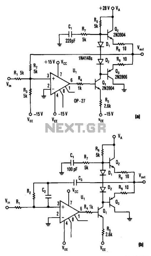
Basic Operational Amplifier Configurations
Operational amplifiers (op-amps) are fundamental building blocks in analog circuit design. Common configurations like inverting, non-inverting, differential amplifiers, and integrators are widely used for signal processing and amplification tasks. These configurations serve as the core components for more complex analog circuit designs.
Inverting Amplifier
The inverting amplifier configuration provides signal inversion and amplification capabilities, making it versatile for various applications like audio processing and instrumentation.
Non-Inverting Amplifier
Contrary to the inverting configuration, the non-inverting amplifier preserves the signal phase while providing signal amplification, making it suitable for applications where phase reversal is undesirable.
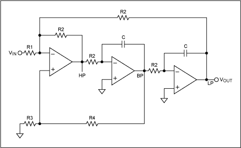
Active Filters
Active filters are integral to analog circuit design as they allow for precise shaping of frequency response characteristics. Butterworth, Chebyshev, and Elliptic filters are common types used for applications requiring specific frequency domain behavior such as audio processing and RF electronics.
Butterworth Filter
The Butterworth filter is known for its maximally flat frequency response in the passband, making it ideal for applications demanding uniform gain over a wide frequency range.
Chebyshev Filter
Chebyshev filters offer steeper roll-off rates in the stopband compared to Butterworth filters, making them suitable for applications where rapid attenuation of specific frequencies is required.
Feedback in Analog Circuits
Feedback mechanisms play a crucial role in stabilizing and controlling analog circuit behavior. Understanding the types of feedback (positive and negative) and their impacts on circuit stability, bandwidth, and gain is essential for designing robust and reliable analog systems.
Negative Feedback
The incorporation of negative feedback in analog circuits improves linearity, stability, and bandwidth while reducing distortion, making it a common technique for enhancing circuit performance.
Positive Feedback
Positive feedback, although less common in analog circuits, can be strategically used to create oscillators, comparators, and hysteresis circuits, adding dynamism and non-linear functionality to circuit designs.
Analog Circuit Design Principles
In electronics, analog circuits play a crucial role in processing continuous signals. Understanding the principles behind analog circuit design is essential for engineers and physicists working on various electronic systems. This section will delve into key concepts and methodologies involved in designing analog circuits with precision and efficiency.
Basic Operational Amplifier Configurations
Operational amplifiers (op-amps) are fundamental building blocks in analog circuit design. Common configurations like inverting, non-inverting, differential amplifiers, and integrators are widely used for signal processing and amplification tasks. These configurations serve as the core components for more complex analog circuit designs.
Inverting Amplifier
The inverting amplifier configuration provides signal inversion and amplification capabilities, making it versatile for various applications like audio processing and instrumentation.
Non-Inverting Amplifier
Contrary to the inverting configuration, the non-inverting amplifier preserves the signal phase while providing signal amplification, making it suitable for applications where phase reversal is undesirable.
Active Filters
Active filters are integral to analog circuit design as they allow for precise shaping of frequency response characteristics. Butterworth, Chebyshev, and Elliptic filters are common types used for applications requiring specific frequency domain behavior such as audio processing and RF electronics.
Butterworth Filter
The Butterworth filter is known for its maximally flat frequency response in the passband, making it ideal for applications demanding uniform gain over a wide frequency range.
Chebyshev Filter
Chebyshev filters offer steeper roll-off rates in the stopband compared to Butterworth filters, making them suitable for applications where rapid attenuation of specific frequencies is required.
Feedback in Analog Circuits
Feedback mechanisms play a crucial role in stabilizing and controlling analog circuit behavior. Understanding the types of feedback (positive and negative) and their impacts on circuit stability, bandwidth, and gain is essential for designing robust and reliable analog systems.
Negative Feedback
The incorporation of negative feedback in analog circuits improves linearity, stability, and bandwidth while reducing distortion, making it a common technique for enhancing circuit performance.
Positive Feedback
Positive feedback, although less common in analog circuits, can be strategically used to create oscillators, comparators, and hysteresis circuits, adding dynamism and non-linear functionality to circuit designs.
2.3 Digital Circuit Design Principles
Digital circuit design principles form the backbone of modern electronic systems. These principles involve the use of binary signals to represent data and execute logical operations. In this section, we will delve into the foundational concepts that underpin digital circuit design and explore their significance in creating complex electronic systems.
Binary Representation and Logic Gates
Digital circuits operate with binary signals, where '0' represents a low voltage level and '1' signifies a high voltage level. The interactions between these binary signals are governed by logic gates. These gates, such as AND, OR, and NOT gates, facilitate the manipulation of binary data through logical operations.
Understanding the behavior of logic gates is essential for designing circuits that perform specific functions accurately. By combining various gates in different configurations, engineers can create complex circuits capable of executing intricate tasks.
Combinational and Sequential Logic
Combinational logic circuits produce an output solely based on the current input signals, without any memory elements. In contrast, sequential logic circuits incorporate memory elements like flip-flops to store information, leading to sequential operation.
The distinction between combinational and sequential logic is fundamental in digital circuit design, as it dictates how data is processed within a system. Utilizing a combination of these two types of logic enables the creation of sophisticated electronic devices with versatile functionalities.
Boolean Algebra and Karnaugh Maps
Boolean algebra provides a mathematical framework for analyzing and simplifying logical expressions in digital circuits. By applying Boolean laws and theorems, engineers can optimize circuit designs, reducing complexity and improving efficiency.
Karnaugh maps offer a graphical method for minimizing Boolean functions, aiding in the simplification of logic circuits. These maps provide a visual representation of the relationships between input and output variables, facilitating the design of compact and streamlined circuits.
State Machines and Finite State Automata
State machines play a crucial role in digital circuit design by defining the behavior of sequential logic circuits. These machines exhibit various states and transitions determined by input signals, enabling the implementation of complex control and decision-making processes.
Finite state automata represent the behavior of systems with a finite number of states, illustrating their dynamic nature and response to input stimuli. Understanding state machines and automata is essential for developing efficient and reliable digital systems with predefined functionality.
2.4 Mixed-Signal Systems
Mixed-signal systems play a crucial role in modern electronic devices, combining both analog and digital components to achieve versatile and high-performance functionalities. Understanding the interactions between analog and digital signals is vital in designing efficient systems for a wide range of applications. ### Analog-Digital Conversion One fundamental aspect of mixed-signal systems is analog-to-digital conversion (ADC) and digital-to-analog conversion (DAC). ADCs sample and convert continuous analog signals into discrete digital data, while DACs perform the reverse operation by converting digital signals back into analog form. These processes are essential in various applications, such as audio processing, instrumentation, and communication systems. ### Signal Integrity and Noise Considerations In mixed-signal systems, maintaining signal integrity is challenging due to the presence of noise, distortion, and interference. Designing robust systems involves consideration of noise sources, such as thermal noise, quantization noise, and crosstalk. Mitigating these effects requires advanced signal processing techniques, effective grounding strategies, and careful component selection to ensure accurate signal processing. ### Interface Circuitry and Signal Conditioning The interface circuitry in mixed-signal systems is crucial for bridging the gap between analog and digital domains. Signal conditioning circuits, such as amplifiers, filters, and modulators, are used to preprocess analog signals before digitization and vice versa. These circuits enhance signal quality, reduce noise, and improve the overall system performance. ### Real-World Applications Mixed-signal systems find extensive applications in areas such as telecommunications, sensor networks, and consumer electronics. For example, in telecommunications, digital radio receivers use mixed-signal processing to convert radio frequency signals into digital information. Similarly, sensor interfaces in industrial automation rely on mixed-signal systems to process and interpret sensor data accurately. ### Advanced Control Techniques Advanced control techniques, including digital signal processing (DSP) algorithms and feedback control systems, are often integrated into mixed-signal systems to achieve precise control and optimization. These techniques enable adaptive filtering, system identification, and dynamic signal processing, enhancing the system's functionality and performance. ### System Integration Challenges Integrating analog and digital components in a mixed-signal system poses unique challenges related to compatibility, power efficiency, and noise immunity. System designers must carefully address issues such as signal coupling, power supply distribution, and mixed-signal layout to ensure seamless operation and reliable performance. ### Future Trends and Innovations The field of mixed-signal systems is continuously evolving, driven by advancements in semiconductor technologies, signal processing algorithms, and system-level integration. Emerging trends focus on increasing system complexity, improving energy efficiency, and enhancing signal processing capabilities for next-generation applications in Internet of Things (IoT), wearable devices, and embedded systems. ### Mathematical Perspective From a mathematical standpoint, mixed-signal systems involve complex equations related to signal processing, system modeling, and control theory. Mathematical models for ADCs, DACs, filter designs, and system optimization play a critical role in analyzing and designing mixed-signal systems with high precision and performance.2.4 Mixed-Signal Systems
Mixed-signal systems play a crucial role in modern electronic devices, combining both analog and digital components to achieve versatile and high-performance functionalities. Understanding the interactions between analog and digital signals is vital in designing efficient systems for a wide range of applications. ### Analog-Digital Conversion One fundamental aspect of mixed-signal systems is analog-to-digital conversion (ADC) and digital-to-analog conversion (DAC). ADCs sample and convert continuous analog signals into discrete digital data, while DACs perform the reverse operation by converting digital signals back into analog form. These processes are essential in various applications, such as audio processing, instrumentation, and communication systems. ### Signal Integrity and Noise Considerations In mixed-signal systems, maintaining signal integrity is challenging due to the presence of noise, distortion, and interference. Designing robust systems involves consideration of noise sources, such as thermal noise, quantization noise, and crosstalk. Mitigating these effects requires advanced signal processing techniques, effective grounding strategies, and careful component selection to ensure accurate signal processing. ### Interface Circuitry and Signal Conditioning The interface circuitry in mixed-signal systems is crucial for bridging the gap between analog and digital domains. Signal conditioning circuits, such as amplifiers, filters, and modulators, are used to preprocess analog signals before digitization and vice versa. These circuits enhance signal quality, reduce noise, and improve the overall system performance. ### Real-World Applications Mixed-signal systems find extensive applications in areas such as telecommunications, sensor networks, and consumer electronics. For example, in telecommunications, digital radio receivers use mixed-signal processing to convert radio frequency signals into digital information. Similarly, sensor interfaces in industrial automation rely on mixed-signal systems to process and interpret sensor data accurately. ### Advanced Control Techniques Advanced control techniques, including digital signal processing (DSP) algorithms and feedback control systems, are often integrated into mixed-signal systems to achieve precise control and optimization. These techniques enable adaptive filtering, system identification, and dynamic signal processing, enhancing the system's functionality and performance. ### System Integration Challenges Integrating analog and digital components in a mixed-signal system poses unique challenges related to compatibility, power efficiency, and noise immunity. System designers must carefully address issues such as signal coupling, power supply distribution, and mixed-signal layout to ensure seamless operation and reliable performance. ### Future Trends and Innovations The field of mixed-signal systems is continuously evolving, driven by advancements in semiconductor technologies, signal processing algorithms, and system-level integration. Emerging trends focus on increasing system complexity, improving energy efficiency, and enhancing signal processing capabilities for next-generation applications in Internet of Things (IoT), wearable devices, and embedded systems. ### Mathematical Perspective From a mathematical standpoint, mixed-signal systems involve complex equations related to signal processing, system modeling, and control theory. Mathematical models for ADCs, DACs, filter designs, and system optimization play a critical role in analyzing and designing mixed-signal systems with high precision and performance.3. Requirements Analysis
3.1 Requirements Analysis
Electronic systems are complex arrangements of interconnected components that work together to perform specific functions. In order to design and implement efficient electronic systems, a thorough requirements analysis is necessary. This process involves understanding the objectives, constraints, and specifications of the system to be developed. ### Understanding System Objectives At the core of requirements analysis is the identification of system objectives. These objectives define the purpose and functionality of the electronic system. Engineers must collaborate closely with clients or stakeholders to clearly define and prioritize these objectives. This step ensures that the system design aligns with the intended use case and performance expectations. ### Determining System Constraints In addition to objectives, system constraints play a crucial role in shaping the design process. Constraints may include limitations on budget, size, power consumption, environmental conditions, and regulatory standards. Engineers must meticulously identify and consider these constraints during the requirements analysis phase to ensure that the final system meets all necessary specifications. ### Establishing Functional Specifications Functional specifications outline the specific features and behaviors that the electronic system must exhibit. These specifications are derived from the system objectives and constraints. By clearly defining the required functions, performance metrics, and operational modes, engineers can create a detailed roadmap for the system design and implementation process. ### Performance Metrics and Trade-offs Analyzing performance metrics such as speed, accuracy, reliability, and energy efficiency is essential in requirements analysis. Engineers must balance these metrics against each other and make informed trade-offs to optimize the overall system performance. Understanding the interplay between different performance parameters is crucial for achieving an efficient and effective electronic system design. ### Real-World Applications The principles of requirements analysis extend beyond theoretical concepts and are directly applicable to real-world electronic system design. Whether developing consumer electronics, industrial automation systems, or aerospace technology, engineers rely on thorough requirements analysis to ensure the successful implementation of complex electronic systems in various applications.- IEEE Xplore Digital Library — Access a vast collection of research articles and technical papers on electronic systems and engineering.
- Microelectronics Journal - ScienceDirect — Explore cutting-edge research in microelectronics and electronic system design.
- Sensors Magazine — Stay updated on sensor technologies and their integration into electronic systems.
- EDN Network — Dive into in-depth articles and analysis on electronic design and innovation.
- Electronic Design — Access resources and insights on electronic system design and development.
- IEEE Spectrum — Explore the latest advancements and trends in electronic engineering and technology.
- ResearchGate — Connect with researchers and access a wide range of publications on electronic systems.
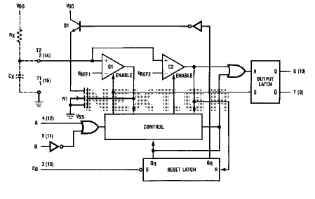
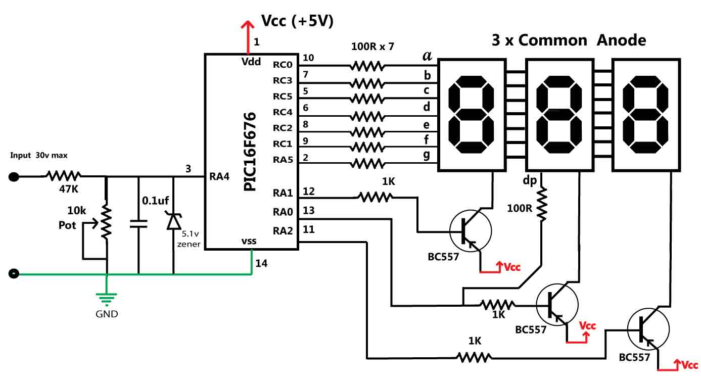
3.2 Schematic Design Techniques
In the realm of electronic systems, effective schematic design lies at the heart of innovation and functionality. Translating abstract concepts into tangible circuit schematics requires finesse and precision. Advanced-level readers, such as engineers and physicists, often delve into intricate design techniques to optimize performance and reliability. Let's explore some key strategies that elevate schematic design to an art form.
Understanding Hierarchical Schematic Design
Hierarchical design organizes complex systems into manageable modules, facilitating a structured approach to circuit development. By breaking down circuits into subsystems, designers enhance clarity, reusability, and scalability. This technique not only streamlines the design process but also promotes collaboration among team members working on different sections of the same project.
Signal Integrity Considerations
Ensuring signal integrity is paramount in high-frequency applications where signal quality is susceptible to degradation. By implementing proper grounding techniques, controlled impedance routing, and signal isolation methods, designers mitigate signal distortion and crosstalk issues. Advanced readers dive deep into the nuances of signal integrity to optimize circuit performance.
Power Distribution Management
Efficient power distribution is essential for maintaining system reliability and performance. Advanced designers meticulously plan power delivery networks, employing techniques such as power decoupling, voltage regulation, and thermal management. By optimizing power distribution, engineers achieve stable operation and mitigate potential failures due to inadequate power supply design.
Layout Optimization for Noise Immunity
Layout plays a crucial role in minimizing electromagnetic interference (EMI) and ensuring noise immunity in electronic systems. Advanced techniques include proper component placement, routing guidelines, and partitioning strategies. By strategically arranging components and traces, designers attenuate noise sources and enhance the overall electromagnetic compatibility (EMC) of the circuit.
Simulation-Based Iterative Design
Simulation tools enable designers to evaluate circuit performance virtually before physical implementation, saving time and resources. Advanced designers conduct rigorous simulations to analyze signal integrity, power distribution, thermal behavior, and EMI susceptibility. Iterative design based on simulation results allows for fine-tuning of the schematic for optimal functionality and performance.
Practical Implementation Insights
Real-world applications often demand innovative solutions to complex design challenges. Advanced readers explore case studies and practical examples that showcase the application of schematic design techniques in cutting-edge electronic systems. By studying real implementations, engineers gain valuable insights into industry best practices and emerging trends in electronic system design.
3.3 Simulation and Prototyping
In electronic systems design, simulation and prototyping play crucial roles in validating concepts and ensuring the functionality of the final product. This subsection delves into the processes involved in simulating electronic systems and prototyping physical implementations.Simulation of Electronic Systems
Simulation software enables engineers to model and analyze electronic circuits before physically constructing them. This process aids in understanding circuit behavior, optimizing performance, and identifying potential issues early in the design phase.Types of Electronic Systems Simulations
- Circuit Simulation: Involves analyzing the behavior of electrical circuits using software tools like SPICE (Simulation Program with Integrated Circuit Emphasis). - Signal Integrity Simulation: Focuses on analyzing and maintaining signal quality in high-speed digital systems to prevent issues like signal distortion or reflections. - Power Integrity Simulation: Evaluates power distribution networks to ensure stable and reliable power delivery to all components in a system.Prototyping Electronic Systems
Prototyping involves building physical representations of the electronic system to test functionality, performance, and integration with other components. This stage often bridges the gap between simulation and actual production.Prototyping Techniques
- Pilot Production: Small-scale manufacturing to assess assembly processes and identify potential production issues. - Breadboarding: Quick and low-cost way of testing circuit designs using breadboards and discrete components. - Printed Circuit Board (PCB) Prototyping: Involves designing and fabricating custom PCBs based on the electronic system's schematic.Benefits of Simulation and Prototyping
- Risk Mitigation: Identifying and resolving design flaws early reduces costly mistakes in later stages. - Performance Optimization: Fine-tuning parameters for optimal system performance and efficiency. - Time Efficiency: Accelerating the design iteration process by quickly identifying and addressing design issues.Real-World Applications
Simulation and prototyping find extensive use in various industries, including aerospace, automotive, telecommunications, and consumer electronics. For instance, in aerospace, simulating complex avionics systems helps ensure the safety and reliability of aircraft components. Remember, a well-executed simulation and prototyping phase can significantly impact the success and performance of electronic systems in practical applications.3.3 Simulation and Prototyping
In electronic systems design, simulation and prototyping play crucial roles in validating concepts and ensuring the functionality of the final product. This subsection delves into the processes involved in simulating electronic systems and prototyping physical implementations.Simulation of Electronic Systems
Simulation software enables engineers to model and analyze electronic circuits before physically constructing them. This process aids in understanding circuit behavior, optimizing performance, and identifying potential issues early in the design phase.Types of Electronic Systems Simulations
- Circuit Simulation: Involves analyzing the behavior of electrical circuits using software tools like SPICE (Simulation Program with Integrated Circuit Emphasis). - Signal Integrity Simulation: Focuses on analyzing and maintaining signal quality in high-speed digital systems to prevent issues like signal distortion or reflections. - Power Integrity Simulation: Evaluates power distribution networks to ensure stable and reliable power delivery to all components in a system.Prototyping Electronic Systems
Prototyping involves building physical representations of the electronic system to test functionality, performance, and integration with other components. This stage often bridges the gap between simulation and actual production.Prototyping Techniques
- Pilot Production: Small-scale manufacturing to assess assembly processes and identify potential production issues. - Breadboarding: Quick and low-cost way of testing circuit designs using breadboards and discrete components. - Printed Circuit Board (PCB) Prototyping: Involves designing and fabricating custom PCBs based on the electronic system's schematic.Benefits of Simulation and Prototyping
- Risk Mitigation: Identifying and resolving design flaws early reduces costly mistakes in later stages. - Performance Optimization: Fine-tuning parameters for optimal system performance and efficiency. - Time Efficiency: Accelerating the design iteration process by quickly identifying and addressing design issues.Real-World Applications
Simulation and prototyping find extensive use in various industries, including aerospace, automotive, telecommunications, and consumer electronics. For instance, in aerospace, simulating complex avionics systems helps ensure the safety and reliability of aircraft components. Remember, a well-executed simulation and prototyping phase can significantly impact the success and performance of electronic systems in practical applications.3.4 Design for Testing and Maintenance
Designing electronic systems for efficient testing and maintenance is crucial in ensuring their reliability and longevity. In this section, we will explore key strategies and considerations for creating electronic systems that are easily testable and maintainable.
Testing Considerations
Testing electronic systems is essential to identify and rectify potential faults or issues. By designing systems with testing in mind, engineers can streamline the testing process and improve overall system reliability.
- Boundary Scan Testing: Implementing boundary scan chains can facilitate testing of individual components on a circuit board, enhancing fault detection capabilities.
- Built-in Self-Test (BIST): Incorporating BIST features in the design allows the system to perform self-diagnostic tests, reducing the need for external test equipment.
Maintenance Strategies
Proper maintenance of electronic systems is crucial for ensuring their optimal performance over time. Designing for maintenance involves creating systems that are easily accessible for troubleshooting and repair.
- Modularity: Breaking down the system into modular components simplifies maintenance by enabling quick replacement of faulty parts.
- Clear Documentation: Providing comprehensive documentation, including circuit diagrams and component specifications, aids in efficient troubleshooting and maintenance.
Real-World Applications
Designing electronic systems for effective testing and maintenance is of utmost importance in various industries, including aerospace, automotive, and telecommunications. By implementing robust testing strategies and maintenance protocols, organizations can enhance system reliability and minimize downtime.
Mathematical Derivation: Signal-to-Noise Ratio (SNR)
3.4 Design for Testing and Maintenance
Designing electronic systems for efficient testing and maintenance is crucial in ensuring their reliability and longevity. In this section, we will explore key strategies and considerations for creating electronic systems that are easily testable and maintainable.
Testing Considerations
Testing electronic systems is essential to identify and rectify potential faults or issues. By designing systems with testing in mind, engineers can streamline the testing process and improve overall system reliability.
- Boundary Scan Testing: Implementing boundary scan chains can facilitate testing of individual components on a circuit board, enhancing fault detection capabilities.
- Built-in Self-Test (BIST): Incorporating BIST features in the design allows the system to perform self-diagnostic tests, reducing the need for external test equipment.
Maintenance Strategies
Proper maintenance of electronic systems is crucial for ensuring their optimal performance over time. Designing for maintenance involves creating systems that are easily accessible for troubleshooting and repair.
- Modularity: Breaking down the system into modular components simplifies maintenance by enabling quick replacement of faulty parts.
- Clear Documentation: Providing comprehensive documentation, including circuit diagrams and component specifications, aids in efficient troubleshooting and maintenance.
Real-World Applications
Designing electronic systems for effective testing and maintenance is of utmost importance in various industries, including aerospace, automotive, and telecommunications. By implementing robust testing strategies and maintenance protocols, organizations can enhance system reliability and minimize downtime.
Mathematical Derivation: Signal-to-Noise Ratio (SNR)
4. Introduction to Control Theory
Introduction to Control Theory
In the realm of electronic systems, control theory plays a pivotal role in overseeing and managing the behavior of dynamic systems. It provides a systematic framework for understanding, analyzing, and optimizing the performance of systems that evolve over time. Control theory is crucial in various fields, including engineering, physics, and automation.
At its core, control theory deals with the manipulation of variables within a system to achieve desired outputs. This subsection delves into the fundamental concepts of control theory, exploring key principles, mathematical models, and real-world applications that underline its significance.
Key Concepts in Control Theory:
- Feedback Control: Involves continuously monitoring the system output and adjusting the input based on the feedback received.
- Open-loop vs. Closed-loop Control: Contrasts between control systems that lack feedback loops (open-loop) and those that incorporate feedback mechanisms (closed-loop).
- Control System Components: Examination of key components such as controllers, actuators, sensors, and plant dynamics.
- Stability and Performance: Discusses stability criteria and performance metrics used to evaluate control systems.
Mathematical Foundations:
Control theory heavily relies on mathematical tools to analyze system behavior and design effective control strategies. Mathematical concepts such as differential equations, Laplace transforms, transfer functions, and state-space representations are essential for modeling and simulating control systems.
Real-World Applications:
Control theory finds applications in diverse domains, including robotics, aerospace engineering, power systems, and automotive systems. For instance, in robotics, control theory governs the movements of robotic arms to perform precise tasks with accuracy and efficiency.
By understanding control theory principles, engineers and researchers can develop sophisticated control algorithms to enhance system performance, stability, and robustness.
4.2 Open-Loop vs Closed-Loop Systems
In electronic systems, the distinction between open-loop and closed-loop systems is fundamental in understanding how feedback control mechanisms work. Let's delve into the mechanisms and advantages of each system. ### Open-Loop Systems Open-loop systems are characterized by the absence of feedback from the output to the input. In these systems, the input directly influences the output without any correction based on the output's actual performance. The lack of feedback makes open-loop systems less adaptable to changes or disturbances in the environment. One classic example of an open-loop system is a microwave oven. When you set the cooking time without any sensors to measure the food's actual temperature, the oven runs for the specified time regardless of whether the food is fully cooked or not. ### Closed-Loop Systems In contrast, closed-loop systems incorporate feedback from the output back to the input to make real-time adjustments based on the system's performance. By continuously monitoring the output and comparing it to the desired response, closed-loop systems can maintain stability, accuracy, and robustness even in the presence of disturbances. A common closed-loop system is the thermostat in a heating system. The thermostat monitors the room temperature and adjusts the heating level to maintain the desired temperature, creating a feedback loop that ensures the system's performance matches the setpoint. #### Key Differences - Feedback Mechanism: Open-loop lacks feedback, while closed-loop incorporates feedback for adjustments. - Accuracy and Stability: Closed-loop systems are typically more accurate and stable due to feedback mechanisms. - Adaptability: Closed-loop systems can adapt to changing conditions, while open-loop systems are fixed. ### Practical Applications The choice between open-loop and closed-loop systems depends on the desired control precision, system complexity, and environmental variability. Closed-loop systems are prevalent in complex control systems like aircraft autopilots, industrial automation, and robotic control, where precision and adaptability are crucial. ### Mathematical Insight To understand the difference mathematically, we can introduce transfer functions and control theory concepts to analyze the behavior of open-loop and closed-loop systems in terms of stability, gain, and response characteristics.4.2 Open-Loop vs Closed-Loop Systems
In electronic systems, the distinction between open-loop and closed-loop systems is fundamental in understanding how feedback control mechanisms work. Let's delve into the mechanisms and advantages of each system. ### Open-Loop Systems Open-loop systems are characterized by the absence of feedback from the output to the input. In these systems, the input directly influences the output without any correction based on the output's actual performance. The lack of feedback makes open-loop systems less adaptable to changes or disturbances in the environment. One classic example of an open-loop system is a microwave oven. When you set the cooking time without any sensors to measure the food's actual temperature, the oven runs for the specified time regardless of whether the food is fully cooked or not. ### Closed-Loop Systems In contrast, closed-loop systems incorporate feedback from the output back to the input to make real-time adjustments based on the system's performance. By continuously monitoring the output and comparing it to the desired response, closed-loop systems can maintain stability, accuracy, and robustness even in the presence of disturbances. A common closed-loop system is the thermostat in a heating system. The thermostat monitors the room temperature and adjusts the heating level to maintain the desired temperature, creating a feedback loop that ensures the system's performance matches the setpoint. #### Key Differences - Feedback Mechanism: Open-loop lacks feedback, while closed-loop incorporates feedback for adjustments. - Accuracy and Stability: Closed-loop systems are typically more accurate and stable due to feedback mechanisms. - Adaptability: Closed-loop systems can adapt to changing conditions, while open-loop systems are fixed. ### Practical Applications The choice between open-loop and closed-loop systems depends on the desired control precision, system complexity, and environmental variability. Closed-loop systems are prevalent in complex control systems like aircraft autopilots, industrial automation, and robotic control, where precision and adaptability are crucial. ### Mathematical Insight To understand the difference mathematically, we can introduce transfer functions and control theory concepts to analyze the behavior of open-loop and closed-loop systems in terms of stability, gain, and response characteristics.4.3 Controllers and Feedback Mechanisms
In electronic systems, controllers and feedback mechanisms play a pivotal role in maintaining stability, accuracy, and desired performance. These components are crucial in regulating various parameters within a system and ensuring optimal functionality. ####Controllers in Electronic Systems
Controllers in electronic systems are devices or algorithms that receive input signals, process them, and produce outputs to control system variables. They manage the behavior of a system to achieve desired objectives. Common types of controllers include Proportional-Integral-Derivative (PID) controllers, state-space controllers, and fuzzy logic controllers. Each type has its unique advantages and applications based on system requirements. ####Feedback Mechanisms
Feedback mechanisms are essential in electronic systems to compare the actual output of a system with the desired output and generate an error signal. This error signal is then used by the controller to adjust the system's operation to minimize discrepancies. Feedback loops can be positive or negative, with negative feedback being the most common in control systems due to its stability-enhancing properties. ####Practical Applications
The utilization of controllers and feedback mechanisms is widespread across various industries, including automotive, aerospace, robotics, and process control. In automotive systems, controllers regulate engine parameters for optimal performance and efficiency. In aerospace, feedback mechanisms ensure precise control of flight surfaces. Robotics heavily rely on controllers to execute programmed tasks accurately. ####Mathematical Formulations
Mathematically, controllers often involve differential equations, transfer functions, and Laplace transforms to model system behavior accurately. Understanding the mathematics behind controllers and feedback mechanisms is crucial for designing robust control systems. Let's consider a simple PID controller formulation to illustrate its operation:4.3 Controllers and Feedback Mechanisms
In electronic systems, controllers and feedback mechanisms play a pivotal role in maintaining stability, accuracy, and desired performance. These components are crucial in regulating various parameters within a system and ensuring optimal functionality. ####Controllers in Electronic Systems
Controllers in electronic systems are devices or algorithms that receive input signals, process them, and produce outputs to control system variables. They manage the behavior of a system to achieve desired objectives. Common types of controllers include Proportional-Integral-Derivative (PID) controllers, state-space controllers, and fuzzy logic controllers. Each type has its unique advantages and applications based on system requirements. ####Feedback Mechanisms
Feedback mechanisms are essential in electronic systems to compare the actual output of a system with the desired output and generate an error signal. This error signal is then used by the controller to adjust the system's operation to minimize discrepancies. Feedback loops can be positive or negative, with negative feedback being the most common in control systems due to its stability-enhancing properties. ####Practical Applications
The utilization of controllers and feedback mechanisms is widespread across various industries, including automotive, aerospace, robotics, and process control. In automotive systems, controllers regulate engine parameters for optimal performance and efficiency. In aerospace, feedback mechanisms ensure precise control of flight surfaces. Robotics heavily rely on controllers to execute programmed tasks accurately. ####Mathematical Formulations
Mathematically, controllers often involve differential equations, transfer functions, and Laplace transforms to model system behavior accurately. Understanding the mathematics behind controllers and feedback mechanisms is crucial for designing robust control systems. Let's consider a simple PID controller formulation to illustrate its operation:4.4 Applications of Control Systems in Electronics
Control systems play a pivotal role in the realm of electronics, enabling precise regulation and monitoring of various parameters in electronic devices and systems. In this section, we will delve into the practical applications of control systems within the domain of electronics, showcasing their significance in achieving stability, efficiency, and optimal performance. ### Introduction to Control Systems in Electronics Control systems are integral components in electronic devices, providing the ability to regulate and maintain desired output conditions. These systems utilize feedback mechanisms to adjust system variables and ensure steady-state operation. By incorporating control theory principles, electronic systems can effectively manage diverse functionalities, ranging from simple temperature regulation to complex robotic movements. ### Feedback Control in Electronic Systems Feedback control mechanisms are widely employed in electronics to maintain system stability and accuracy. By comparing actual system outputs with reference values, feedback loops can dynamically adjust control signals to achieve desired performance levels. This results in enhanced precision, responsiveness, and robustness in electronic systems across various applications. ### PID Controllers in Electronics Proportional-Integral-Derivative (PID) controllers represent a cornerstone of control systems in electronics. These controllers combine proportional, integral, and derivative control actions to effectively regulate system behavior. PID controllers find extensive use in applications such as motor control, temperature regulation, and process automation, offering versatile performance optimization capabilities. ### Applications of Control Systems in Electronics 1. Motor Speed Control: Control systems are instrumental in regulating the speed and direction of electric motors, ensuring efficient operation in diverse industrial and consumer applications. 2. Temperature Regulation: Electronic control systems play a crucial role in maintaining precise temperature levels in devices like ovens, refrigerators, and climate control systems. 3. Robotics and Automation: Control systems enable precise control of robotic movements, facilitating automation in manufacturing, assembly lines, and unmanned vehicles. 4. Power Electronics: Control systems optimize power conversion processes in electronic devices, enhancing energy efficiency and performance. 5. Communication Systems: Feedback control mechanisms enhance signal processing in communication systems, ensuring reliable transmission and reception of data. 6. Embedded Systems: Control algorithms are implemented in embedded systems to regulate system responses, enhancing functionality and reliability in various applications. ### Case Study: Adaptive Control in Electronics An illustrative example of adaptive control in electronics involves the deployment of self-tuning algorithms to adjust system parameters based on varying operating conditions. This adaptive approach enhances system flexibility and responsiveness, enabling electronic devices to adapt seamlessly to changing requirements and environmental factors. By integrating control systems into electronic designs, engineers and researchers can optimize performance, enhance stability, and achieve precise control over system dynamics. The diverse applications of control systems in electronics underscore their indispensable role in modern technological advancements. ---4.4 Applications of Control Systems in Electronics
Control systems play a pivotal role in the realm of electronics, enabling precise regulation and monitoring of various parameters in electronic devices and systems. In this section, we will delve into the practical applications of control systems within the domain of electronics, showcasing their significance in achieving stability, efficiency, and optimal performance. ### Introduction to Control Systems in Electronics Control systems are integral components in electronic devices, providing the ability to regulate and maintain desired output conditions. These systems utilize feedback mechanisms to adjust system variables and ensure steady-state operation. By incorporating control theory principles, electronic systems can effectively manage diverse functionalities, ranging from simple temperature regulation to complex robotic movements. ### Feedback Control in Electronic Systems Feedback control mechanisms are widely employed in electronics to maintain system stability and accuracy. By comparing actual system outputs with reference values, feedback loops can dynamically adjust control signals to achieve desired performance levels. This results in enhanced precision, responsiveness, and robustness in electronic systems across various applications. ### PID Controllers in Electronics Proportional-Integral-Derivative (PID) controllers represent a cornerstone of control systems in electronics. These controllers combine proportional, integral, and derivative control actions to effectively regulate system behavior. PID controllers find extensive use in applications such as motor control, temperature regulation, and process automation, offering versatile performance optimization capabilities. ### Applications of Control Systems in Electronics 1. Motor Speed Control: Control systems are instrumental in regulating the speed and direction of electric motors, ensuring efficient operation in diverse industrial and consumer applications. 2. Temperature Regulation: Electronic control systems play a crucial role in maintaining precise temperature levels in devices like ovens, refrigerators, and climate control systems. 3. Robotics and Automation: Control systems enable precise control of robotic movements, facilitating automation in manufacturing, assembly lines, and unmanned vehicles. 4. Power Electronics: Control systems optimize power conversion processes in electronic devices, enhancing energy efficiency and performance. 5. Communication Systems: Feedback control mechanisms enhance signal processing in communication systems, ensuring reliable transmission and reception of data. 6. Embedded Systems: Control algorithms are implemented in embedded systems to regulate system responses, enhancing functionality and reliability in various applications. ### Case Study: Adaptive Control in Electronics An illustrative example of adaptive control in electronics involves the deployment of self-tuning algorithms to adjust system parameters based on varying operating conditions. This adaptive approach enhances system flexibility and responsiveness, enabling electronic devices to adapt seamlessly to changing requirements and environmental factors. By integrating control systems into electronic designs, engineers and researchers can optimize performance, enhance stability, and achieve precise control over system dynamics. The diverse applications of control systems in electronics underscore their indispensable role in modern technological advancements. ---5. Basic Principles of Communication
5.1 Basic Principles of Communication
In electronic systems, communication plays a fundamental role in transmitting information from one point to another. This process involves the encoding, transmission, and decoding of signals. Understanding the basic principles of communication is crucial for designing efficient and reliable communication systems. ####1. Signal Representation
At the core of communication systems is the concept of signal representation. Signals can be analog or digital, carrying information in different forms. Analog signals are continuous in nature, representing real-world phenomena, while digital signals are discrete, represented by binary values (0s and 1s). The choice between analog and digital signals depends on factors like noise resilience, bandwidth efficiency, and ease of processing. ####2. Modulation Techniques
Modulation is the process of varying one or more properties of a carrier signal in accordance with an information signal. This technique allows for the efficient transmission of signals over a communication channel. Common modulation techniques include Amplitude Modulation (AM), Frequency Modulation (FM), and Phase Modulation (PM). Each modulation scheme has its advantages and is used based on specific system requirements. ####3. Transmission Media
Communication systems rely on various transmission media to propagate signals. These can be guided (e.g., optical fibers, copper wires) or unguided (e.g., air for wireless communication). The choice of transmission medium impacts factors like signal attenuation, bandwidth, and data rate. Understanding the characteristics of different transmission media is crucial for designing robust communication systems. ####4. Channel Capacity and Noise
Channel capacity refers to the maximum rate of data transmission over a communication channel. Noise, on the other hand, introduces errors and limits the achievable data rate. Measures like Signal-to-Noise Ratio (SNR) and channel coding are used to improve communication reliability in the presence of noise. Optimizing channel capacity while mitigating noise effects is essential for efficient communication system design. ####5. Multiplexing and Demultiplexing
Multiplexing allows multiple signals to be combined and transmitted over a shared channel, maximizing the utilization of the available bandwidth. Demultiplexing involves separating these signals at the receiving end. Techniques like Time-Division Multiplexing (TDM) and Frequency-Division Multiplexing (FDM) are commonly used in communication systems to enable the simultaneous transmission of multiple streams of data. ####6. Error Detection and Correction
In communication systems, errors can occur during signal transmission due to noise, interference, or channel impairments. Error detection techniques like parity checks and Cyclic Redundancy Checks (CRC) identify errors, while error correction codes like Hamming codes and Reed-Solomon codes can correct these errors. Implementing robust error detection and correction mechanisms is critical for ensuring data integrity in communication systems. ####7. Spread Spectrum Techniques
Spread spectrum techniques spread the signal over a wider bandwidth, providing benefits such as increased security, interference resistance, and multiple access capabilities. Direct Sequence Spread Spectrum (DSSS) and Frequency Hopping Spread Spectrum (FHSS) are popular spread spectrum techniques used in various communication standards like Wi-Fi and Bluetooth. Understanding spread spectrum methods is key to designing secure and reliable communication systems. ---5.1 Basic Principles of Communication
In electronic systems, communication plays a fundamental role in transmitting information from one point to another. This process involves the encoding, transmission, and decoding of signals. Understanding the basic principles of communication is crucial for designing efficient and reliable communication systems. ####1. Signal Representation
At the core of communication systems is the concept of signal representation. Signals can be analog or digital, carrying information in different forms. Analog signals are continuous in nature, representing real-world phenomena, while digital signals are discrete, represented by binary values (0s and 1s). The choice between analog and digital signals depends on factors like noise resilience, bandwidth efficiency, and ease of processing. ####2. Modulation Techniques
Modulation is the process of varying one or more properties of a carrier signal in accordance with an information signal. This technique allows for the efficient transmission of signals over a communication channel. Common modulation techniques include Amplitude Modulation (AM), Frequency Modulation (FM), and Phase Modulation (PM). Each modulation scheme has its advantages and is used based on specific system requirements. ####3. Transmission Media
Communication systems rely on various transmission media to propagate signals. These can be guided (e.g., optical fibers, copper wires) or unguided (e.g., air for wireless communication). The choice of transmission medium impacts factors like signal attenuation, bandwidth, and data rate. Understanding the characteristics of different transmission media is crucial for designing robust communication systems. ####4. Channel Capacity and Noise
Channel capacity refers to the maximum rate of data transmission over a communication channel. Noise, on the other hand, introduces errors and limits the achievable data rate. Measures like Signal-to-Noise Ratio (SNR) and channel coding are used to improve communication reliability in the presence of noise. Optimizing channel capacity while mitigating noise effects is essential for efficient communication system design. ####5. Multiplexing and Demultiplexing
Multiplexing allows multiple signals to be combined and transmitted over a shared channel, maximizing the utilization of the available bandwidth. Demultiplexing involves separating these signals at the receiving end. Techniques like Time-Division Multiplexing (TDM) and Frequency-Division Multiplexing (FDM) are commonly used in communication systems to enable the simultaneous transmission of multiple streams of data. ####6. Error Detection and Correction
In communication systems, errors can occur during signal transmission due to noise, interference, or channel impairments. Error detection techniques like parity checks and Cyclic Redundancy Checks (CRC) identify errors, while error correction codes like Hamming codes and Reed-Solomon codes can correct these errors. Implementing robust error detection and correction mechanisms is critical for ensuring data integrity in communication systems. ####7. Spread Spectrum Techniques
Spread spectrum techniques spread the signal over a wider bandwidth, providing benefits such as increased security, interference resistance, and multiple access capabilities. Direct Sequence Spread Spectrum (DSSS) and Frequency Hopping Spread Spectrum (FHSS) are popular spread spectrum techniques used in various communication standards like Wi-Fi and Bluetooth. Understanding spread spectrum methods is key to designing secure and reliable communication systems. ---5.2 Modulation Techniques
In electronic systems, modulation techniques play a crucial role in transmitting information efficiently over communication channels. Various modulation schemes are used to encode information onto carrier signals, enabling the transmission of data, audio, and video signals. Understanding modulation is essential for engineers and researchers working in telecommunications, wireless networks, and signal processing.
Key Concepts
Modulation involves modifying one or more properties of a high-frequency carrier signal in accordance with the signal that carries the information to be transmitted. This alteration allows the signal to be efficiently transmitted over short or long distances without significant loss or interference.
Types of Modulation
There are several types of modulation techniques, including:
- Amplitude Modulation (AM): Varied amplitude of the carrier signal encodes information.
- Frequency Modulation (FM): Information is encoded in the carrier signal's frequency deviation.
- Phase Modulation (PM): Information is represented by changes in the carrier signal's phase.
- Quadrature Amplitude Modulation (QAM): Combines both amplitude and phase modulation to transmit data efficiently.
Signal Bandwidth and Modulation
Each modulation technique has unique characteristics, affecting the bandwidth required for transmission and the system's overall performance. Engineers must carefully select the appropriate modulation scheme based on the application's requirements, trade-offs, and constraints.
Applications and Practical Relevance
Modulation techniques are foundational in various communication systems, including radio broadcasting, satellite communications, cellular networks, and digital television. Understanding modulation principles allows engineers to design robust and efficient communication systems that meet the demands of modern technology.
Mathematical Formulation
Where:
- $$s(t)$$: Modulated signal
- $$A_c$$: Amplitude of the carrier signal
- $$m$$: Modulation index
- $$f(t)$$: Baseband signal
- $$f_c$$: Carrier frequency
- $$\phi$$: Initial phase of the carrier signal
This equation represents the general form of amplitude modulation, where the baseband signal $$f(t)$$ modulates the carrier signal at frequency $$f_c$$ with modulation index $$m$$.
5.2 Modulation Techniques
In electronic systems, modulation techniques play a crucial role in transmitting information efficiently over communication channels. Various modulation schemes are used to encode information onto carrier signals, enabling the transmission of data, audio, and video signals. Understanding modulation is essential for engineers and researchers working in telecommunications, wireless networks, and signal processing.
Key Concepts
Modulation involves modifying one or more properties of a high-frequency carrier signal in accordance with the signal that carries the information to be transmitted. This alteration allows the signal to be efficiently transmitted over short or long distances without significant loss or interference.
Types of Modulation
There are several types of modulation techniques, including:
- Amplitude Modulation (AM): Varied amplitude of the carrier signal encodes information.
- Frequency Modulation (FM): Information is encoded in the carrier signal's frequency deviation.
- Phase Modulation (PM): Information is represented by changes in the carrier signal's phase.
- Quadrature Amplitude Modulation (QAM): Combines both amplitude and phase modulation to transmit data efficiently.
Signal Bandwidth and Modulation
Each modulation technique has unique characteristics, affecting the bandwidth required for transmission and the system's overall performance. Engineers must carefully select the appropriate modulation scheme based on the application's requirements, trade-offs, and constraints.
Applications and Practical Relevance
Modulation techniques are foundational in various communication systems, including radio broadcasting, satellite communications, cellular networks, and digital television. Understanding modulation principles allows engineers to design robust and efficient communication systems that meet the demands of modern technology.
Mathematical Formulation
Where:
- $$s(t)$$: Modulated signal
- $$A_c$$: Amplitude of the carrier signal
- $$m$$: Modulation index
- $$f(t)$$: Baseband signal
- $$f_c$$: Carrier frequency
- $$\phi$$: Initial phase of the carrier signal
This equation represents the general form of amplitude modulation, where the baseband signal $$f(t)$$ modulates the carrier signal at frequency $$f_c$$ with modulation index $$m$$.
5.3 Wireless Communication Technologies
In this section, we delve into the fascinating world of wireless communication technologies, which have revolutionized how we exchange information and data over large distances without the need for physical wires.
Introduction to Wireless Communication
Wireless communication involves the transmission of data over a distance without the need for physical electrical conductors. This method of communication has become ubiquitous in modern society, enabling various technologies such as mobile phones, Wi-Fi networks, and satellite communication systems.
Electromagnetic Spectrum
At the heart of wireless communication lies the electromagnetic spectrum, which encompasses all forms of electromagnetic radiation. This spectrum is divided into various frequency bands, each with unique properties and applications in communication technologies.
Modulation Techniques
To transmit data wirelessly, modulation techniques are employed to encode information onto carrier waves. Common modulation schemes include Amplitude Modulation (AM), Frequency Modulation (FM), and Phase Shift Keying (PSK), each offering distinct advantages in different scenarios.
Wireless Standards
Various wireless communication standards have been developed to ensure interoperability between devices and networks. Standards like Bluetooth, Wi-Fi (IEEE 802.11), and cellular standards (e.g., 4G LTE, 5G) play crucial roles in enabling seamless wireless connectivity.
Propagation and Interference in Wireless Systems
Propagation of wireless signals involves the transmission of electromagnetic waves through various mediums, including air, water, and space. Understanding signal propagation characteristics is essential for designing efficient wireless communication systems that can overcome interference and signal degradation.
Antenna Technologies
Antennas play a critical role in wireless communication, acting as both transmitters and receivers of electromagnetic signals. Different antenna designs, such as dipole antennas, patch antennas, and parabolic antennas, are used based on the specific requirements of the wireless system.
Signal Processing in Wireless Communication
Signal processing techniques are employed to enhance the quality of wireless signals, mitigate interference, and improve data transmission efficiency. Digital signal processing algorithms play a key role in modern wireless systems, enabling advanced modulation and encoding schemes.
Security and Encryption in Wireless Networks
Ensuring the security of wireless communication is paramount to protect sensitive data from unauthorized access and cyber-attacks. Encryption protocols like WPA2, WPA3, and SSL/TLS are used to secure wireless networks and safeguard transmitted information.
5.4 Network Protocols and Standards
In the realm of electronic systems, network protocols and standards play a crucial role in ensuring efficient communication between devices. These protocols govern the rules and formats used for data exchange, enabling seamless connectivity and interoperability across various networks.
Network Protocols
Network protocols define the procedures for transmitting and receiving data packets over a network. They encompass a set of rules that govern communication between devices, ensuring reliable and secure data transfer. One of the fundamental aspects of network protocols is the layered structure, commonly illustrated by the OSI model, which conceptualizes networking functions into distinct layers.
At the physical layer, protocols like Ethernet and Wi-Fi govern the transmission of raw data bits. Moving up the layers, protocols such as IP (Internet Protocol) manage addressing and routing, while transport layer protocols like TCP (Transmission Control Protocol) ensure reliable delivery of data. Application layer protocols like HTTP (Hypertext Transfer Protocol) facilitate specific services, such as web browsing.
Network Standards
Network standards define the specifications and guidelines that devices must adhere to in order to achieve interoperability and seamless communication. These standards ensure that devices from different manufacturers can communicate effectively, promoting the development of diverse and interconnected networks.
Standards bodies like the IEEE (Institute of Electrical and Electronics Engineers) play a crucial role in establishing and maintaining network standards. For instance, the IEEE 802.11 standard governs wireless LAN technologies, while the IEEE 802.3 standard defines Ethernet for wired networks. Compliance with these standards enables devices to transmit and receive data using a common language, fostering compatibility and scalability.
Real-World Applications
The significance of network protocols and standards extends beyond theoretical frameworks, finding practical applications in various domains. For example, in industrial automation, protocols like Modbus facilitate communication between sensors, actuators, and control systems, enabling efficient monitoring and control of manufacturing processes. In the realm of telecommunications, standards like GSM (Global System for Mobile Communications) ensure seamless connectivity and interoperability across mobile networks, enabling global communication.
Understanding network protocols and standards is essential for designing robust and efficient communication systems, ensuring reliable data exchange and enabling seamless connectivity in diverse applications.
6. Introduction to Power Conversion
Introduction to Power Conversion
In electronic systems, power conversion plays a crucial role in transforming electrical energy from one form to another efficiently. This process is fundamental for various applications, including renewable energy systems, electric vehicles, and consumer electronics. Understanding power conversion principles is essential for engineers and physicists to design efficient and reliable electronic systems.
Basic Concepts of Power Conversion
Power conversion involves converting electrical energy from a source into a form suitable for the load. The efficiency of a power conversion system is a critical factor as it determines the amount of energy wasted during the process. Key concepts in power conversion include:
- Power: The rate at which energy is transferred or transformed. It is given by the product of voltage and current, i.e., $$ P = VI \cos(\theta) $$.
- Efficiency: The ratio of output power to input power, reflecting how effectively energy is converted.
- Converter Topologies: Various circuit configurations used to convert one form of electrical energy to another, such as buck, boost, and buck-boost converters.
- Control Techniques: Methods to regulate the power conversion process, ensuring stability, accuracy, and fast response.
Applications of Power Conversion
Power conversion is ubiquitous in modern electronic systems. Some practical applications include:
- Renewable Energy Systems: Converting solar or wind energy into usable electrical power for grid integration.
- Electric Vehicles: Converting battery or grid power to drive electric motors efficiently.
- Consumer Electronics: Adapting power sources to match the requirements of smartphones, laptops, and other portable devices.
By mastering the principles of power conversion, engineers can design energy-efficient systems that meet the demands of diverse applications.
6.2 Power Supply Design
Advanced energy-efficient electronic systems rely heavily on well-designed power supplies to ensure proper operation and performance. In this section, we will delve into the intricacies of power supply design, considering the efficiency, stability, and performance of these crucial components. Power supply design involves meticulous considerations of voltage regulation, current sourcing, efficiency optimization, and noise reduction. Engineers and researchers often face challenges in balancing these factors to achieve the desired power delivery characteristics.Design Objectives
When embarking on power supply design, engineers must establish clear design objectives to guide the process effectively. These objectives typically include: 1. Voltage Regulation: Ensuring a stable output voltage under varying load conditions is essential for the proper functioning of electronic systems. 2. Efficiency: Maximizing the efficiency of power conversion minimizes energy wastage and heat generation, crucial for both performance and environmental reasons. 3. Noise Minimization: Reducing electrical noise in the power supply output is vital to prevent interference with sensitive electronic components.Topology Selection
Selecting the appropriate power supply topology is a critical decision in the design process. Common topologies include: 1. Linear Power Supplies: Known for their simplicity and low output noise, linear power supplies are suitable for applications where efficiency is not the primary concern. 2. Switched-Mode Power Supplies (SMPS): SMPS offer high efficiency by rapidly switching power transistors on and off, making them ideal for energy-sensitive applications.Control and Regulation
Effective control and regulation mechanisms in power supplies are essential for maintaining stable output voltages and currents. Methods include: 1. Feedback Loops: Implementing feedback loops using operational amplifiers ensures precise regulation by comparing the actual output with a reference signal. 2. Pulse-Width Modulation (PWM): PWM techniques adjust the duty cycle of the switching signal to control the output voltage in SMPS.Efficiency Enhancement
Efficiency improvements in power supplies can be achieved through various means, such as: 1. Power Factor Correction (PFC): PFC techniques improve the power factor of the system, minimizing reactive power and maximizing efficiency. 2. Load-Switching Techniques: Implementing intelligent load-switching strategies can optimize power delivery based on the current system requirements.Practical Considerations
In real-world applications, power supply designers must account for factors like thermal management, component selection, and protection features to ensure system reliability and longevity. By integrating advanced technologies and applying innovative design strategies, engineers can develop power supplies that meet the evolving demands of modern electronic systems.6.2 Power Supply Design
Advanced energy-efficient electronic systems rely heavily on well-designed power supplies to ensure proper operation and performance. In this section, we will delve into the intricacies of power supply design, considering the efficiency, stability, and performance of these crucial components. Power supply design involves meticulous considerations of voltage regulation, current sourcing, efficiency optimization, and noise reduction. Engineers and researchers often face challenges in balancing these factors to achieve the desired power delivery characteristics.Design Objectives
When embarking on power supply design, engineers must establish clear design objectives to guide the process effectively. These objectives typically include: 1. Voltage Regulation: Ensuring a stable output voltage under varying load conditions is essential for the proper functioning of electronic systems. 2. Efficiency: Maximizing the efficiency of power conversion minimizes energy wastage and heat generation, crucial for both performance and environmental reasons. 3. Noise Minimization: Reducing electrical noise in the power supply output is vital to prevent interference with sensitive electronic components.Topology Selection
Selecting the appropriate power supply topology is a critical decision in the design process. Common topologies include: 1. Linear Power Supplies: Known for their simplicity and low output noise, linear power supplies are suitable for applications where efficiency is not the primary concern. 2. Switched-Mode Power Supplies (SMPS): SMPS offer high efficiency by rapidly switching power transistors on and off, making them ideal for energy-sensitive applications.Control and Regulation
Effective control and regulation mechanisms in power supplies are essential for maintaining stable output voltages and currents. Methods include: 1. Feedback Loops: Implementing feedback loops using operational amplifiers ensures precise regulation by comparing the actual output with a reference signal. 2. Pulse-Width Modulation (PWM): PWM techniques adjust the duty cycle of the switching signal to control the output voltage in SMPS.Efficiency Enhancement
Efficiency improvements in power supplies can be achieved through various means, such as: 1. Power Factor Correction (PFC): PFC techniques improve the power factor of the system, minimizing reactive power and maximizing efficiency. 2. Load-Switching Techniques: Implementing intelligent load-switching strategies can optimize power delivery based on the current system requirements.Practical Considerations
In real-world applications, power supply designers must account for factors like thermal management, component selection, and protection features to ensure system reliability and longevity. By integrating advanced technologies and applying innovative design strategies, engineers can develop power supplies that meet the evolving demands of modern electronic systems.6.3 Motor Control Technologies
In the realm of electronic systems, motor control technologies serve as a fundamental aspect enabling precise manipulation of mechanical systems. Whether in industrial automation, robotics, or electric vehicles, the efficient operation of motors is paramount. This section delves into the intricate details of motor control, shedding light on the underlying principles and advanced techniques utilized in various applications.
Principles of Motor Control
Motor control revolves around managing the speed, torque, and direction of a motor. In essence, it involves converting electrical signals into mechanical motion. The dynamic response, efficiency, and accuracy of motor control systems are crucial factors determining their effectiveness in diverse scenarios.
Types of Motor Control Systems
Different motor types necessitate varying control strategies. From simple DC motors to complex synchronous motors, each category demands tailored methodologies to achieve optimal performance. Moreover, modern advancements have led to the development of sophisticated motor control techniques, such as field-oriented control (FOC) and direct torque control (DTC).
Advanced Control Algorithms
The implementation of advanced control algorithms plays a pivotal role in enhancing the efficiency and precision of motor systems. Proportional-Integral-Derivative (PID) controllers, dead-time compensation, and feedforward control are among the strategies utilized to regulate motor behavior, offering superior responsiveness and stability under varying operating conditions.
Amidst the plethora of control algorithms available, model predictive control (MPC) stands out for its predictive nature, enabling preemptive adjustments to optimize motor performance. By considering system dynamics and constraints, MPC facilitates robust and agile control, particularly beneficial in applications requiring stringent performance criteria.
Emerging Technologies in Motor Control
The field of motor control continues to evolve, incorporating innovations like machine learning and artificial intelligence to revolutionize conventional control paradigms. Neural networks, reinforcement learning, and adaptive control mechanisms hold promise in enhancing motor efficiency, fault detection, and adaptability in dynamic environments.
Furthermore, the amalgamation of Internet of Things (IoT) concepts with motor control has paved the way for interconnected systems capable of remote monitoring, predictive maintenance, and autonomous operation. Such synergies enable smart motor control applications across industries, augmenting productivity and reliability.
6.3 Motor Control Technologies
In the realm of electronic systems, motor control technologies serve as a fundamental aspect enabling precise manipulation of mechanical systems. Whether in industrial automation, robotics, or electric vehicles, the efficient operation of motors is paramount. This section delves into the intricate details of motor control, shedding light on the underlying principles and advanced techniques utilized in various applications.
Principles of Motor Control
Motor control revolves around managing the speed, torque, and direction of a motor. In essence, it involves converting electrical signals into mechanical motion. The dynamic response, efficiency, and accuracy of motor control systems are crucial factors determining their effectiveness in diverse scenarios.
Types of Motor Control Systems
Different motor types necessitate varying control strategies. From simple DC motors to complex synchronous motors, each category demands tailored methodologies to achieve optimal performance. Moreover, modern advancements have led to the development of sophisticated motor control techniques, such as field-oriented control (FOC) and direct torque control (DTC).
Advanced Control Algorithms
The implementation of advanced control algorithms plays a pivotal role in enhancing the efficiency and precision of motor systems. Proportional-Integral-Derivative (PID) controllers, dead-time compensation, and feedforward control are among the strategies utilized to regulate motor behavior, offering superior responsiveness and stability under varying operating conditions.
Amidst the plethora of control algorithms available, model predictive control (MPC) stands out for its predictive nature, enabling preemptive adjustments to optimize motor performance. By considering system dynamics and constraints, MPC facilitates robust and agile control, particularly beneficial in applications requiring stringent performance criteria.
Emerging Technologies in Motor Control
The field of motor control continues to evolve, incorporating innovations like machine learning and artificial intelligence to revolutionize conventional control paradigms. Neural networks, reinforcement learning, and adaptive control mechanisms hold promise in enhancing motor efficiency, fault detection, and adaptability in dynamic environments.
Furthermore, the amalgamation of Internet of Things (IoT) concepts with motor control has paved the way for interconnected systems capable of remote monitoring, predictive maintenance, and autonomous operation. Such synergies enable smart motor control applications across industries, augmenting productivity and reliability.
7. Internet of Things (IoT) Applications
7.1 Internet of Things (IoT) Applications
The Internet of Things (IoT) has revolutionized how electronic systems interact with the physical world. In this advanced-level discussion, we delve into the practical applications of IoT in various domains. ###Smart Homes and Buildings
IoT has enabled the creation of smart environments where devices communicate to enhance efficiency and convenience. In smart homes, IoT devices like smart thermostats, lighting systems, and security cameras can be controlled remotely for energy savings and enhanced security. ###Industrial Automation
Within industrial settings, IoT plays a crucial role in optimizing processes through real-time monitoring and control. For instance, sensors embedded in manufacturing equipment can collect data on performance metrics to ensure smooth operations and preemptive maintenance. ###Healthcare and Wearable Technology
IoT applications in healthcare have led to the development of wearable devices that can track vital signs, monitor patient activities, and even administer medication. This technology enables personalized healthcare solutions and remote patient monitoring. ###Smart Agriculture
In agriculture, IoT devices such as soil moisture sensors, weather stations, and drone technology are used to optimize crop yields. Farmers can make data-driven decisions based on real-time information collected from these devices, leading to increased efficiency and sustainability. ###Transportation and Logistics
IoT plays a pivotal role in enhancing transportation systems by providing real-time tracking and monitoring of vehicles, optimizing routes, and improving fleet management. This technology ensures efficient logistics operations and enhanced customer service. ###Energy Management
The integration of IoT in energy management systems allows for remote monitoring of energy consumption, predictive maintenance of equipment, and automation of energy-saving mechanisms. This contributes to sustainable energy practices and cost-efficient operations. ###Environmental Monitoring
IoT devices are extensively used for environmental monitoring purposes, such as air quality sensors, water quality monitoring systems, and wildlife tracking devices. These applications aid in assessing environmental conditions, conservation efforts, and data-driven policymaking. By exploring these diverse IoT applications, we witness the transformative impact of interconnected electronic systems in various sectors, paving the way for a more connected and intelligent future.7.1 Internet of Things (IoT) Applications
The Internet of Things (IoT) has revolutionized how electronic systems interact with the physical world. In this advanced-level discussion, we delve into the practical applications of IoT in various domains. ###Smart Homes and Buildings
IoT has enabled the creation of smart environments where devices communicate to enhance efficiency and convenience. In smart homes, IoT devices like smart thermostats, lighting systems, and security cameras can be controlled remotely for energy savings and enhanced security. ###Industrial Automation
Within industrial settings, IoT plays a crucial role in optimizing processes through real-time monitoring and control. For instance, sensors embedded in manufacturing equipment can collect data on performance metrics to ensure smooth operations and preemptive maintenance. ###Healthcare and Wearable Technology
IoT applications in healthcare have led to the development of wearable devices that can track vital signs, monitor patient activities, and even administer medication. This technology enables personalized healthcare solutions and remote patient monitoring. ###Smart Agriculture
In agriculture, IoT devices such as soil moisture sensors, weather stations, and drone technology are used to optimize crop yields. Farmers can make data-driven decisions based on real-time information collected from these devices, leading to increased efficiency and sustainability. ###Transportation and Logistics
IoT plays a pivotal role in enhancing transportation systems by providing real-time tracking and monitoring of vehicles, optimizing routes, and improving fleet management. This technology ensures efficient logistics operations and enhanced customer service. ###Energy Management
The integration of IoT in energy management systems allows for remote monitoring of energy consumption, predictive maintenance of equipment, and automation of energy-saving mechanisms. This contributes to sustainable energy practices and cost-efficient operations. ###Environmental Monitoring
IoT devices are extensively used for environmental monitoring purposes, such as air quality sensors, water quality monitoring systems, and wildlife tracking devices. These applications aid in assessing environmental conditions, conservation efforts, and data-driven policymaking. By exploring these diverse IoT applications, we witness the transformative impact of interconnected electronic systems in various sectors, paving the way for a more connected and intelligent future.7.2 Artificial Intelligence in Electronics
Artificial intelligence (AI) has revolutionized various industries, including electronics. In this section, we will explore how AI is integrated into electronic systems to enhance functionality, efficiency, and adaptability. AI algorithms enable electronic devices to learn from data, make decisions, and perform tasks without explicit programming. This capability has far-reaching implications for advanced-level readers in engineering, physics, research, and beyond. Let's delve into the key aspects and applications of AI in electronics. ### Artificial Neural Networks (ANNs) Artificial Neural Networks are a fundamental component of AI in electronics. These computational models are inspired by the structure and function of the human brain, consisting of interconnected nodes that process information. ANNs excel in tasks such as pattern recognition, classification, and prediction within electronic systems. Let's explore the mathematical underpinnings and practical implementations of ANNs in electronic devices. ### Evolutionary Algorithms in Electronics Evolutionary algorithms, a subset of AI techniques, mimic natural processes like mutation and selection to optimize electronic systems. By iteratively improving solutions based on a fitness function, evolutionary algorithms enable electronic devices to self-adjust and enhance performance over time. We will examine how these algorithms are applied in circuit design, signal processing, and system optimization. ### Reinforcement Learning in Electronic Control Systems Reinforcement learning is a powerful AI paradigm where agents learn to make sequential decisions by interacting with their environment. In electronic control systems, reinforcement learning enables devices to adapt to dynamic conditions, optimize energy usage, and self-regulate operations. Through real-world case studies, we will elucidate how reinforcement learning algorithms are transforming electronic control systems. ### Swarm Intelligence for Electronic Networks Swarm intelligence algorithms draw inspiration from collective behaviors observed in nature, where individuals work cooperatively to achieve shared goals. In electronic networks, swarm intelligence techniques optimize communication protocols, routing algorithms, and resource allocation. We will discuss the principles behind swarm intelligence and its applications in networked electronic systems. ### Practical Applications of AI in Electronics The integration of AI in electronics has led to innovative applications across diverse domains, including autonomous vehicles, industrial automation, healthcare devices, and smart homes. By leveraging AI capabilities, electronic systems can adapt to complex environments, anticipate user preferences, and enhance overall performance. We will explore cutting-edge applications and emerging trends in AI-driven electronics. The marriage of AI and electronics holds immense potential for future technological advancements, offering unparalleled flexibility, efficiency, and intelligence to electronic systems. By embracing AI-driven approaches, advanced-level readers can stay at the forefront of innovation in the dynamic field of electronics.7.2 Artificial Intelligence in Electronics
Artificial intelligence (AI) has revolutionized various industries, including electronics. In this section, we will explore how AI is integrated into electronic systems to enhance functionality, efficiency, and adaptability. AI algorithms enable electronic devices to learn from data, make decisions, and perform tasks without explicit programming. This capability has far-reaching implications for advanced-level readers in engineering, physics, research, and beyond. Let's delve into the key aspects and applications of AI in electronics. ### Artificial Neural Networks (ANNs) Artificial Neural Networks are a fundamental component of AI in electronics. These computational models are inspired by the structure and function of the human brain, consisting of interconnected nodes that process information. ANNs excel in tasks such as pattern recognition, classification, and prediction within electronic systems. Let's explore the mathematical underpinnings and practical implementations of ANNs in electronic devices. ### Evolutionary Algorithms in Electronics Evolutionary algorithms, a subset of AI techniques, mimic natural processes like mutation and selection to optimize electronic systems. By iteratively improving solutions based on a fitness function, evolutionary algorithms enable electronic devices to self-adjust and enhance performance over time. We will examine how these algorithms are applied in circuit design, signal processing, and system optimization. ### Reinforcement Learning in Electronic Control Systems Reinforcement learning is a powerful AI paradigm where agents learn to make sequential decisions by interacting with their environment. In electronic control systems, reinforcement learning enables devices to adapt to dynamic conditions, optimize energy usage, and self-regulate operations. Through real-world case studies, we will elucidate how reinforcement learning algorithms are transforming electronic control systems. ### Swarm Intelligence for Electronic Networks Swarm intelligence algorithms draw inspiration from collective behaviors observed in nature, where individuals work cooperatively to achieve shared goals. In electronic networks, swarm intelligence techniques optimize communication protocols, routing algorithms, and resource allocation. We will discuss the principles behind swarm intelligence and its applications in networked electronic systems. ### Practical Applications of AI in Electronics The integration of AI in electronics has led to innovative applications across diverse domains, including autonomous vehicles, industrial automation, healthcare devices, and smart homes. By leveraging AI capabilities, electronic systems can adapt to complex environments, anticipate user preferences, and enhance overall performance. We will explore cutting-edge applications and emerging trends in AI-driven electronics. The marriage of AI and electronics holds immense potential for future technological advancements, offering unparalleled flexibility, efficiency, and intelligence to electronic systems. By embracing AI-driven approaches, advanced-level readers can stay at the forefront of innovation in the dynamic field of electronics.7.3 Sustainability in Electronic Design
In the realm of electronic systems, sustainability has become an increasingly critical factor in design and manufacturing processes. As advanced-level readers, understanding the principles and implications of sustainable electronic design is key to shaping the future of technology.
The Economic and Environmental Impact
Electronic devices have a significant environmental footprint, from their production to disposal. E-waste, resulting from outdated or discarded electronics, poses a severe environmental threat due to hazardous materials such as lead and mercury. Sustainable design practices aim to mitigate this impact not only through product longevity but also through eco-friendly materials and recycling strategies.
Design for Longevity and Upgradability
One fundamental principle of sustainable electronic design is creating products that stand the test of time. This involves designing devices with upgradeable components, repairability in mind, and ensuring compatibility with future technologies. Extending the lifespan of electronics reduces the frequency of replacements, thereby reducing overall waste generation.
Energy Efficiency and Power Management
Efficient energy utilization is a core aspect of sustainability in electronic systems. Incorporating power-saving features, optimizing circuit designs for lower energy consumption, and implementing smart power management algorithms are strategies that help reduce the environmental impact of electronics while lowering operational costs for users.
Materials Selection and Lifecycle Analysis
Choosing environmentally friendly materials and conducting thorough lifecycle assessments are crucial steps in sustainable electronic design. Materials with lower environmental impact, recyclable components, and efficient disposal strategies contribute to minimizing the overall carbon footprint of electronic products.
Case Study: Fairphone
An exemplary case of sustainable electronic design is the Fairphone, a modular smartphone designed with longevity and repairability in mind. By enabling users to easily replace components such as the battery and screen, Fairphone promotes extended device lifespan and reduced electronic waste generation.
Where:
- Efficiency (Eefficiency): The efficiency of the electronic system
- Output Power (Pout): The power delivered by the system
- Input Power (Pin): The power consumed by the system
By integrating sustainable principles into electronic design, engineers and researchers play a crucial role in shaping a more environmentally conscious and efficient technological landscape.
---7.3 Sustainability in Electronic Design
In the realm of electronic systems, sustainability has become an increasingly critical factor in design and manufacturing processes. As advanced-level readers, understanding the principles and implications of sustainable electronic design is key to shaping the future of technology.
The Economic and Environmental Impact
Electronic devices have a significant environmental footprint, from their production to disposal. E-waste, resulting from outdated or discarded electronics, poses a severe environmental threat due to hazardous materials such as lead and mercury. Sustainable design practices aim to mitigate this impact not only through product longevity but also through eco-friendly materials and recycling strategies.
Design for Longevity and Upgradability
One fundamental principle of sustainable electronic design is creating products that stand the test of time. This involves designing devices with upgradeable components, repairability in mind, and ensuring compatibility with future technologies. Extending the lifespan of electronics reduces the frequency of replacements, thereby reducing overall waste generation.
Energy Efficiency and Power Management
Efficient energy utilization is a core aspect of sustainability in electronic systems. Incorporating power-saving features, optimizing circuit designs for lower energy consumption, and implementing smart power management algorithms are strategies that help reduce the environmental impact of electronics while lowering operational costs for users.
Materials Selection and Lifecycle Analysis
Choosing environmentally friendly materials and conducting thorough lifecycle assessments are crucial steps in sustainable electronic design. Materials with lower environmental impact, recyclable components, and efficient disposal strategies contribute to minimizing the overall carbon footprint of electronic products.
Case Study: Fairphone
An exemplary case of sustainable electronic design is the Fairphone, a modular smartphone designed with longevity and repairability in mind. By enabling users to easily replace components such as the battery and screen, Fairphone promotes extended device lifespan and reduced electronic waste generation.
Where:
- Efficiency (Eefficiency): The efficiency of the electronic system
- Output Power (Pout): The power delivered by the system
- Input Power (Pin): The power consumed by the system
By integrating sustainable principles into electronic design, engineers and researchers play a crucial role in shaping a more environmentally conscious and efficient technological landscape.
---Future of Electronic Systems
In the realm of electronic systems, the future holds tremendous promise and potential for advanced technologies and applications. As we delve into the forefront of innovation, several key areas are shaping the landscape of electronic systems. ### Quantum Computing Revolution One of the most groundbreaking advancements on the horizon is the potential of quantum computing to revolutionize computational power. Quantum computers leverage quantum bits or qubits, which can exist in multiple states simultaneously, enabling exponential increases in processing capabilities. This shift towards quantum supremacy could unlock new possibilities in cryptography, machine learning, and complex simulations. ### Neuromorphic Computing Inspired by the human brain's architecture, neuromorphic computing aims to develop artificial neural networks that mimic biological neurons and synapses. This approach holds the promise of ultra-efficient and adaptive computing systems capable of learning and self-optimizing tasks. Neuromorphic systems have the potential to revolutionize AI applications, edge computing, and robotics. ### Emergence of 6G Networks The evolution towards 6G networks is anticipated to usher in a new era of ultra-fast, ultra-reliable wireless connectivity. With speeds surpassing 5G by orders of magnitude, 6G networks could enable seamless augmented reality, holographic communication, and massive IoT deployments. This next generation of wireless technology is poised to transform communication infrastructures globally. ### Advancements in Nanoelectronics Nanoelectronics is pushing the boundaries of miniaturization, enabling the development of ultra-compact and energy-efficient electronic devices. With advancements in nanomaterials and nanofabrication techniques, future electronic systems may incorporate nanoscale components for enhanced performance and functionality. Nanoelectronics paves the way for wearable electronics, implantable devices, and IoT sensor networks. ### Integration of AI and Edge Computing The convergence of artificial intelligence (AI) and edge computing is set to reshape the landscape of electronic systems by enabling real-time data processing and decision-making at the network's edge. By deploying AI algorithms directly on edge devices, such as sensors and actuators, electronic systems can autonomously respond to changing environments, optimize energy consumption, and enhance overall system performance. ### Resilient and Secure Systems The future of electronic systems places a strong emphasis on building resilient and secure architectures to combat cyber threats and ensure data integrity. Robust encryption mechanisms, secure firmware updates, and hardware-based security features are integral to safeguarding electronic systems against malicious attacks and vulnerabilities. As electronic systems become more interconnected, ensuring robust cybersecurity measures is paramount. In essence, the future of electronic systems is characterized by transformative technologies that promise to reshape industries, drive innovation, and empower the next wave of digital evolution.Future of Electronic Systems
In the realm of electronic systems, the future holds tremendous promise and potential for advanced technologies and applications. As we delve into the forefront of innovation, several key areas are shaping the landscape of electronic systems. ### Quantum Computing Revolution One of the most groundbreaking advancements on the horizon is the potential of quantum computing to revolutionize computational power. Quantum computers leverage quantum bits or qubits, which can exist in multiple states simultaneously, enabling exponential increases in processing capabilities. This shift towards quantum supremacy could unlock new possibilities in cryptography, machine learning, and complex simulations. ### Neuromorphic Computing Inspired by the human brain's architecture, neuromorphic computing aims to develop artificial neural networks that mimic biological neurons and synapses. This approach holds the promise of ultra-efficient and adaptive computing systems capable of learning and self-optimizing tasks. Neuromorphic systems have the potential to revolutionize AI applications, edge computing, and robotics. ### Emergence of 6G Networks The evolution towards 6G networks is anticipated to usher in a new era of ultra-fast, ultra-reliable wireless connectivity. With speeds surpassing 5G by orders of magnitude, 6G networks could enable seamless augmented reality, holographic communication, and massive IoT deployments. This next generation of wireless technology is poised to transform communication infrastructures globally. ### Advancements in Nanoelectronics Nanoelectronics is pushing the boundaries of miniaturization, enabling the development of ultra-compact and energy-efficient electronic devices. With advancements in nanomaterials and nanofabrication techniques, future electronic systems may incorporate nanoscale components for enhanced performance and functionality. Nanoelectronics paves the way for wearable electronics, implantable devices, and IoT sensor networks. ### Integration of AI and Edge Computing The convergence of artificial intelligence (AI) and edge computing is set to reshape the landscape of electronic systems by enabling real-time data processing and decision-making at the network's edge. By deploying AI algorithms directly on edge devices, such as sensors and actuators, electronic systems can autonomously respond to changing environments, optimize energy consumption, and enhance overall system performance. ### Resilient and Secure Systems The future of electronic systems places a strong emphasis on building resilient and secure architectures to combat cyber threats and ensure data integrity. Robust encryption mechanisms, secure firmware updates, and hardware-based security features are integral to safeguarding electronic systems against malicious attacks and vulnerabilities. As electronic systems become more interconnected, ensuring robust cybersecurity measures is paramount. In essence, the future of electronic systems is characterized by transformative technologies that promise to reshape industries, drive innovation, and empower the next wave of digital evolution.8. Recommended Textbooks
8.1 Recommended Textbooks
- Fundamentals of Applied Electromagnetics — By Fawwaz T. Ulaby and Umberto Ravaioli, this textbook presents clear explanations of electromagnetic principles and includes updated real-world applications to enhance learning.
- Microelectronic Circuits — Authored by Adel S. Sedra and Kenneth C. Smith, offering a comprehensive exploration of microelectronic circuit design and analysis, ideal for students and professionals in electronics.
- System Dynamics: Modeling, Simulation, and Control of Mechatronic Systems — By Dean C. Karnopp et al., this book provides thorough insights into system dynamics applied to mechatronic design and includes various simulation tools.
- Electronic Devices — Written by Thomas L. Floyd, this book is a definitive guide to electronic devices, offering strong theoretical foundations coupled with practical applications in circuits.
- Modern Digital Electronics — R.P. Jain delves into digital electronic principles, focusing on systematic digital design methodologies and the evolution of modern digital systems.
- Simulation of Industrial Processes for Control Engineers — By Philip J. Thomas, it serves as a comprehensive resource on simulating various industrial processes, enforcing practical applications of control engineering.
- Physics of Semiconductor Devices — Authored by Simon M. Sze and Kwok K. Ng, this classic text explores the fundamental physics and operational principles of semiconductor devices extensively.
8.2 Relevant Research Papers
- Design of a High Efficiency Power Amplifier — Explores innovative design techniques for power amplifiers to achieve high efficiency, crucial for enhancing wireless communication systems. The paper includes detailed theoretical frameworks supported by simulation results.
- Electronic System Level Design — This paper presents methodologies for electronic system-level design that improve the efficiency of complex systems. It delves into abstraction levels, offering strategies for optimizing system architecture.
- Fault Detection in Embedded Systems — Discusses advanced techniques for fault detection and recovery in embedded systems, ensuring reliability and robustness in critical applications. It provides insights into both hardware and software strategies.
- Optimization of Microgrid Operations — A valuable resource on optimizing microgrid operations through electronic systems management, addressing integration challenges of renewable energy sources and ensuring effective load balancing.
- Understanding IEEE Methods for Development Systems — An accessible guide for IEEE methods applicable to electronic system development, this resource offers practical insights into standard practices and innovative methods.
- High-Speed Digital Design Techniques — Focuses on design processes and strategies for high-speed digital circuits, emphasizing signal integrity, timing closure, and sophisticated modelling for electronic systems.
- Energy-Efficient Electronic Systems — Discusses the development of energy-efficient electronic systems, with a focus on minimizing energy consumption while maximizing performance. Offers comprehensive reviews of recent technological advances.
8.3 Online Resources and Tutorials
In the realm of electronic systems, staying updated with the latest technological advancements and methodologies is crucial for advanced learners and professionals. The internet is a vast repository of knowledge, offering a plethora of resources and tutorials that can enhance understanding and provide practical insights. This section will guide you through some of the most valuable online resources, focusing on their utility for deepening your expertise in electronic systems.Benefits of Online Learning Resources for Electronic Systems
Online platforms provide immense value by offering diverse content formats such as video tutorials, interactive simulations, forums, and comprehensive articles. These resources facilitate the following:- Self-paced Learning: Cater to personal schedules, allowing learners to progress as per their convenience.
- Wide-ranging Content: Covering basic principles to advanced topics across various electronic disciplines.
- Interactive Simulations: Enable users to simulate electronic circuits and systems without physical components.
- Community Interaction: Forums and discussion boards provide opportunities to interact with experts and peers.
Recommended Online Platforms and Tutorials
- All About Circuits — An extensive educational resource for electronics enthusiasts, offering tutorials on electrical engineering topics, interactive simulations, and a vibrant community forum.
- EdX Electronics Courses — Provides a range of online courses from top universities on electronics, featuring structured curricula and interactive components for in-depth learning.
- MIT OpenCourseWare: Electrical Engineering and Computer Science — Offers free course materials from MIT, covering various topics in electronic systems and engineering, perfect for self-learners seeking rigorous academic content.
- Coursera: Electrical Engineering — Features courses from global institutions on advanced electrical engineering topics, with options for certification and peer-reviewed assignments.
- Khan Academy: Electrical Engineering — Provides free tutorials, practice exercises, and personalized learning dashboards to make complex concepts in electronics accessible and engaging.
- The Engineering Mindset - YouTube — A YouTube channel offering detailed videos on practical engineering topics including electronics, ideal for visual learners seeking real-world examples.
- Electronics Stack Exchange — A question-and-answer community for electronics enthusiasts and professionals where users can ask questions and contribute answers to complex electronics problems.
Historical Context and Evolution of Online Learning in Electronics
Online learning platforms have significantly evolved over the past decade. Initially, they primarily served as repositories for textual materials. However, with advancements in internet technology and digital tools, these platforms have expanded to include: - Multimedia Content: Integration of videos, animations, and interactive elements to aid visual and auditory learning. - Global Classroom Experiences: Connecting students and educators worldwide, facilitating diverse perspectives and experiences. - Adaptive Learning Technologies: Offering personalized learning paths based on user progress and understanding levels. The continuous development of these resources reflects the growing reliance on online education in fostering advanced learning and research capabilities in electronic systems. In conclusion, harnessing the power of these vast online resources can significantly augment your knowledge and skills in electronic systems. Stay curious and engaged, and these digital platforms will serve as invaluable companions on your journey to expertise.8.3 Online Resources and Tutorials
In the realm of electronic systems, staying updated with the latest technological advancements and methodologies is crucial for advanced learners and professionals. The internet is a vast repository of knowledge, offering a plethora of resources and tutorials that can enhance understanding and provide practical insights. This section will guide you through some of the most valuable online resources, focusing on their utility for deepening your expertise in electronic systems.Benefits of Online Learning Resources for Electronic Systems
Online platforms provide immense value by offering diverse content formats such as video tutorials, interactive simulations, forums, and comprehensive articles. These resources facilitate the following:- Self-paced Learning: Cater to personal schedules, allowing learners to progress as per their convenience.
- Wide-ranging Content: Covering basic principles to advanced topics across various electronic disciplines.
- Interactive Simulations: Enable users to simulate electronic circuits and systems without physical components.
- Community Interaction: Forums and discussion boards provide opportunities to interact with experts and peers.
Recommended Online Platforms and Tutorials
- All About Circuits — An extensive educational resource for electronics enthusiasts, offering tutorials on electrical engineering topics, interactive simulations, and a vibrant community forum.
- EdX Electronics Courses — Provides a range of online courses from top universities on electronics, featuring structured curricula and interactive components for in-depth learning.
- MIT OpenCourseWare: Electrical Engineering and Computer Science — Offers free course materials from MIT, covering various topics in electronic systems and engineering, perfect for self-learners seeking rigorous academic content.
- Coursera: Electrical Engineering — Features courses from global institutions on advanced electrical engineering topics, with options for certification and peer-reviewed assignments.
- Khan Academy: Electrical Engineering — Provides free tutorials, practice exercises, and personalized learning dashboards to make complex concepts in electronics accessible and engaging.
- The Engineering Mindset - YouTube — A YouTube channel offering detailed videos on practical engineering topics including electronics, ideal for visual learners seeking real-world examples.
- Electronics Stack Exchange — A question-and-answer community for electronics enthusiasts and professionals where users can ask questions and contribute answers to complex electronics problems.
Historical Context and Evolution of Online Learning in Electronics
Online learning platforms have significantly evolved over the past decade. Initially, they primarily served as repositories for textual materials. However, with advancements in internet technology and digital tools, these platforms have expanded to include: - Multimedia Content: Integration of videos, animations, and interactive elements to aid visual and auditory learning. - Global Classroom Experiences: Connecting students and educators worldwide, facilitating diverse perspectives and experiences. - Adaptive Learning Technologies: Offering personalized learning paths based on user progress and understanding levels. The continuous development of these resources reflects the growing reliance on online education in fostering advanced learning and research capabilities in electronic systems. In conclusion, harnessing the power of these vast online resources can significantly augment your knowledge and skills in electronic systems. Stay curious and engaged, and these digital platforms will serve as invaluable companions on your journey to expertise.8.4 Professional Organizations and Societies
In the realm of electronic systems, professional organizations and societies play a pivotal role in fostering innovation, setting industry standards, and providing a platform for education and collaboration. These organizations are crucial for both seasoned professionals and those entering the field. They offer resources ranging from scholarly publications to professional development opportunities, thereby enhancing the knowledge base and skills of their members.The Role of Professional Organizations
Professional organizations and societies in electronic systems serve multiple purposes:- Standardization: These organizations often play a key role in developing and maintaining industry standards, which ensure compatibility and interoperability in electronic systems across different manufacturers and regions.
- Knowledge Sharing: They provide a rich repository of research papers, journals, and publications that keep members informed about the latest advancements and technologies in electronic systems.
- Networking Opportunities: Through conferences, workshops, and seminars, these organizations facilitate networking with other professionals, researchers, and thought leaders in the field.
- Educational Resources: They offer certifications, training programs, and webinars that enhance professional skills and knowledge.
Prominent Organizations in Electronic Systems
Several renowned organizations have shaped and continue to influence the field of electronic systems:IEEE (Institute of Electrical and Electronics Engineers)
The IEEE is the world's largest technical professional organization dedicated to advancing technology for the benefit of humanity. It plays a pivotal role in setting standards for telecommunications, information technology, and power and energy systems. The IEEE produces a vast number of research publications and organizes numerous conferences that cover various facets of electronics and engineering.ACM (Association for Computing Machinery)
While primarily focused on computing, the ACM also significantly impacts the interdisciplinary field of electronic systems, especially in embedded systems and integrated circuits. The ACM is known for its comprehensive digital library and major conferences in computer science and electronics, providing valuable insights and groundbreaking research findings.IEC (International Electrotechnical Commission)
The IEC is a global organization that prepares and publishes international standards for all electrical, electronic, and related technologies. These standards help improve the quality, safety, and efficiency of electronic products worldwide. The IEC's work supports sustainable global economic growth by assuring that electronic systems meet high safety and reliability standards.Benefits of Membership
Joining a professional organization in electronic systems offers numerous advantages:- Professional Development: Access to exclusive content that aids in continuous learning and skill improvement.
- Recognition: Being associated with a reputable organization adds credibility and recognition to professional qualifications.
- Research Opportunities: Opportunities to participate in advanced research collaborations and publishing in accredited journals.
8.4 Professional Organizations and Societies
In the realm of electronic systems, professional organizations and societies play a pivotal role in fostering innovation, setting industry standards, and providing a platform for education and collaboration. These organizations are crucial for both seasoned professionals and those entering the field. They offer resources ranging from scholarly publications to professional development opportunities, thereby enhancing the knowledge base and skills of their members.The Role of Professional Organizations
Professional organizations and societies in electronic systems serve multiple purposes:- Standardization: These organizations often play a key role in developing and maintaining industry standards, which ensure compatibility and interoperability in electronic systems across different manufacturers and regions.
- Knowledge Sharing: They provide a rich repository of research papers, journals, and publications that keep members informed about the latest advancements and technologies in electronic systems.
- Networking Opportunities: Through conferences, workshops, and seminars, these organizations facilitate networking with other professionals, researchers, and thought leaders in the field.
- Educational Resources: They offer certifications, training programs, and webinars that enhance professional skills and knowledge.
Prominent Organizations in Electronic Systems
Several renowned organizations have shaped and continue to influence the field of electronic systems:IEEE (Institute of Electrical and Electronics Engineers)
The IEEE is the world's largest technical professional organization dedicated to advancing technology for the benefit of humanity. It plays a pivotal role in setting standards for telecommunications, information technology, and power and energy systems. The IEEE produces a vast number of research publications and organizes numerous conferences that cover various facets of electronics and engineering.ACM (Association for Computing Machinery)
While primarily focused on computing, the ACM also significantly impacts the interdisciplinary field of electronic systems, especially in embedded systems and integrated circuits. The ACM is known for its comprehensive digital library and major conferences in computer science and electronics, providing valuable insights and groundbreaking research findings.IEC (International Electrotechnical Commission)
The IEC is a global organization that prepares and publishes international standards for all electrical, electronic, and related technologies. These standards help improve the quality, safety, and efficiency of electronic products worldwide. The IEC's work supports sustainable global economic growth by assuring that electronic systems meet high safety and reliability standards.Benefits of Membership
Joining a professional organization in electronic systems offers numerous advantages:- Professional Development: Access to exclusive content that aids in continuous learning and skill improvement.
- Recognition: Being associated with a reputable organization adds credibility and recognition to professional qualifications.
- Research Opportunities: Opportunities to participate in advanced research collaborations and publishing in accredited journals.