
Electronics Thermometer with description
The electronic thermometer circuit utilizes a silicon diode as a temperature sensor due to its reliable characteristics and linear response to temperature changes. The chosen diode, 1N4148, is known for its low forward voltage drop and fast switching capabilities, making it suitable for precise temperature measurements. The operational amplifier serves as a critical component in converting the small voltage changes from the diode into a more significant output voltage that can be easily read and interpreted.
The configuration of the operational amplifier is such that it operates in a non-inverting mode, allowing for amplification of the voltage signal derived from the diode. The resistors R1 and R2, along with the variable resistor VR1, form a voltage divider network that establishes a reference voltage at the non-inverting input of the operational amplifier. This setup ensures that the output voltage from the amplifier is a linear representation of the temperature sensed by the diode.
The feedback loop created by the diode D1 allows for continuous adjustment of the output voltage based on real-time temperature readings. As the temperature varies, the corresponding change in voltage drop across the diode is fed back into the operational amplifier, which adjusts its output accordingly. This dynamic response enables the thermometer to maintain accuracy across its extensive measurement range.
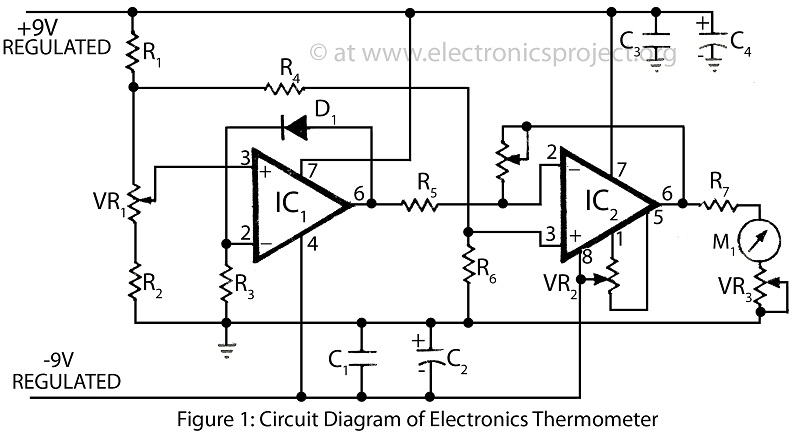
For practical implementation, the output of the operational amplifier can be connected to an analog or digital display for easy reading. Additionally, calibration of the thermometer may be necessary to ensure precision across the specified temperature range. This circuit design is not only effective for medical applications but can also be adapted for industrial temperature monitoring, research, and other fields requiring accurate temperature measurements.Clinical thermometer is only used by doctor because it is difficult to read. Here is a circuit of electronics thermometer used to measure vast range of temperature from -200C to 1250C. This single circuit electronics thermometer can be used to measure differenttemperature. The wide range of temperature measurement made this circuit versatile. This entire circuit Electronics thermometer is built and fabricated around silicon diode D1 (1N4148) and Operational amplifier IC. Diode D1 is used as temperature sensor, temperature determined the value of voltmeter drop across diode i.
e. at room temperature voltage drop is 0. 7V and is reduce by about 2mV/0C. For temperature-to-voltage conversion in electronics thermometer an operational amplifier is used. The input voltage at non-inverting pin 3 of IC1 is fixed by VR1, R1, & R2 where sensor diode D1 forms a feedback path. The output of IC1 is directly depends on the voltage across the diode. 🔗 External reference
Related Circuits
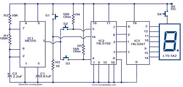
A scoring game circuit is explained with a circuit diagram and circuit parts. The scoring game circuit is designed to track and display scores in a gaming environment. The primary components of this circuit typically include a microcontroller, a score...
For all measurements with the oscilloscope, use the oscilloscope probe with a 10:1 attenuation to minimize measurement errors caused by the capacitance of coaxial cables and the input resistance of the oscilloscope. Problem 1 aims to simulate, build, and...
Design and implementation of a TC237 CCD camera. The TC237 CCD camera is a sophisticated imaging device that utilizes a Charge-Coupled Device (CCD) sensor for capturing high-quality images. The design process involves several key components, including the optical system, electronic...

The circuit illustrated below represents a simple thermometer circuit based on the LM335 temperature sensor. This circuit comprises two main components: the LM335 sensor and its adjustment circuitry. The output from the LM335 generates a voltage of 10 millivolts...
Related components PDF download: ICL7106CD4036. The LCD electronic thermometer circuit is illustrated. The temperature sensor KTY10 exhibits a strong linear relationship between temperature and resistance. Points A and B (Measurement display circuit) can be connected with a 100-meter wire....
Connect all connectors onto the flat cable using a small vice. This creates an instant male-male, male-female, and female-female serial adapter, along with a short extender cord. This tool is essential for those experimenting with serial ports. An additional...
Warning: include(partials/cookie-banner.php): Failed to open stream: Permission denied in /var/www/html/nextgr/view-circuit.php on line 713
Warning: include(): Failed opening 'partials/cookie-banner.php' for inclusion (include_path='.:/usr/share/php') in /var/www/html/nextgr/view-circuit.php on line 713