Electrostatic-detector

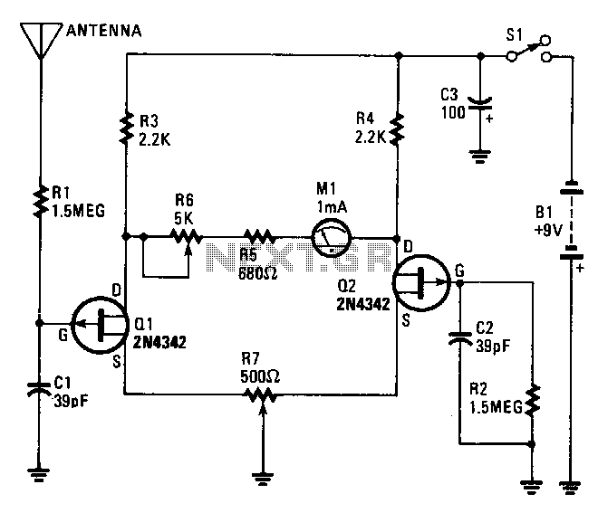
The core of the electroscope consists of two junction FETs, Q1 and Q2, arranged in a balanced-bridge circuit. The gate input of Q1 is connected to a wire pick-up antenna, while the gate of Q2 is connected to the circuit's common ground through resistor R2. This type of bridge circuit provides excellent temperature stability, allowing Q1 to operate in an open-gate configuration. Additionally, potentiometer R7 is employed to balance the bridge circuit, and resistor R6 determines the maximum swing of the meter. Capacitors C1 and C2 are utilized to minimize 60-Hz interference and enhance the short-term stability of the circuit.
The electroscope circuit employs two junction Field-Effect Transistors (FETs), Q1 and Q2, configured in a balanced-bridge topology, which is essential for precise measurements in various applications. The connection of Q1 to the wire pick-up antenna enables it to detect minute electrical signals, while Q2's grounding through resistor R2 ensures that the circuit maintains a stable reference point, crucial for accurate readings.
The balanced-bridge configuration is particularly advantageous due to its inherent temperature stability. This characteristic allows Q1 to function in an open-gate mode, thereby enhancing its sensitivity to input signals without the influence of temperature variations. The use of potentiometer R7 to balance the bridge circuit is vital; it allows for fine-tuning of the circuit to ensure that both FETs operate optimally under varying conditions.
Resistor R6 plays a critical role in defining the maximum swing of the meter, which is indicative of the sensitivity and range of the electroscope. By adjusting R6, the user can calibrate the meter's response to better suit the specific application or environment in which the electroscope is deployed.
Furthermore, the inclusion of capacitors C1 and C2 serves to filter out unwanted 60-Hz noise, which is often present in electronic environments due to AC power sources. This filtering action not only improves the accuracy of the measurements but also contributes to the overall stability of the circuit in short-term operations. Together, these components create a robust electroscope design capable of reliable performance in detecting and measuring electrical signals.The heart of the electroscope is the two junction FETs Ql and Q2 connected in a balanced-bridge circuit. The gate input of Ql is connected to the wire pick-up antenna, while Q2"s gate is tied to the circuit"s common ground through R2.
That type of bridge circuit offers excellent temperature stability; therefore, Ql is allowed to operate in an open-gate configuration. Potentiometer R7 is used to balance the bridge circuit, and R6 sets the maximum meter swing. Capacitors Cl and C2 help to reduce the 60-Hz pickup and add to the short-term stability of the circuit.