
ElektroblockCircuit Using 12V Power Supply
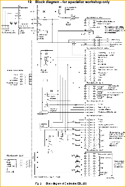
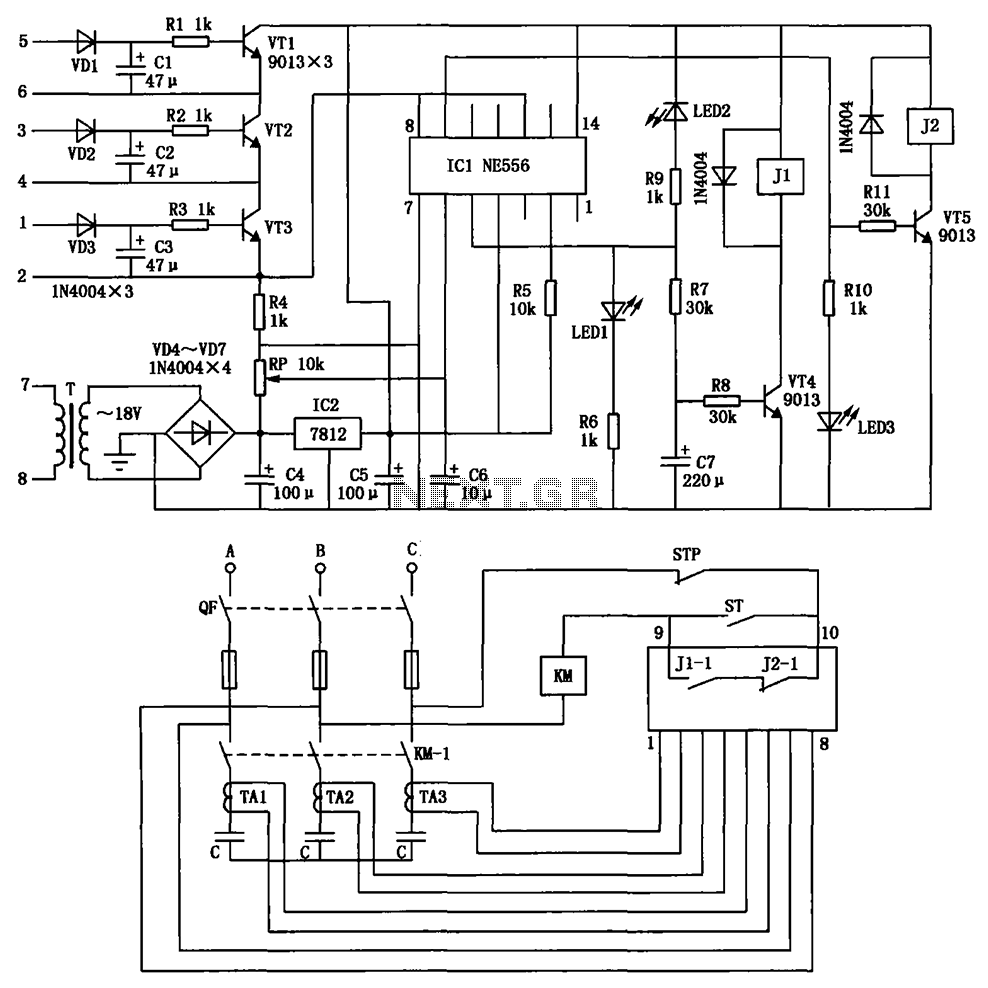
The Elektroblock circuit is designed to operate with a 12V power supply, which is a common voltage level in many electronic applications. The circuit incorporates an 18 A LAS 1218 component, which is likely a power switch or relay that can handle significant current loads. This component is essential for controlling higher power devices within the circuit.
The circuit diagram typically includes various control and monitoring functions, which could involve sensors, indicators, and control switches. These elements work together to provide real-time feedback on the system's performance and operational status. For instance, the inclusion of LEDs can indicate the operational state of the circuit, while sensors may monitor parameters such as temperature or current flow.
To ensure proper operation, the circuit should be designed with appropriate protection mechanisms, such as fuses or circuit breakers, to prevent damage from overcurrent conditions. Additionally, filtering capacitors may be included to stabilize the power supply and reduce noise, enhancing the reliability of the circuit.
Overall, the Elektroblock circuit is a versatile design suitable for various applications where control and monitoring are essential, and it leverages the robust performance characteristics of the LAS 1218 component to manage significant electrical loads efficiently.The following circuit shows about Elektroblock Circuit Diagram Using 12V Power Supply. Features: Other control and monitoring functions, The 18 A LAS 1218 .. 🔗 External reference
Related Circuits
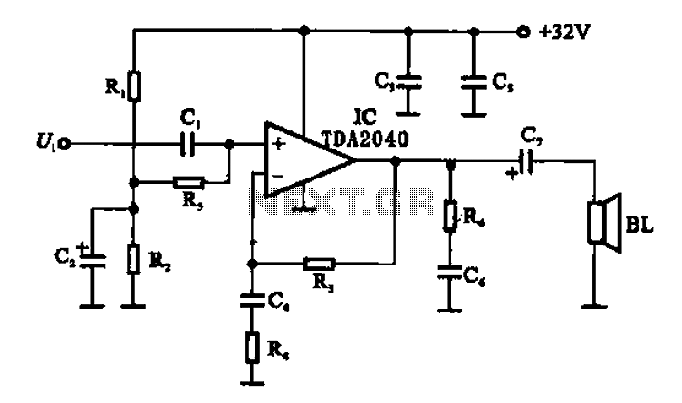
An integrated power amplifier TDA2040 is used in an OTL (Output Transformer-Less) power amplifier circuit, which operates with a +3V single supply as the working voltage. This circuit has a voltage gain of 30 dB (approximately 32 times magnification),...
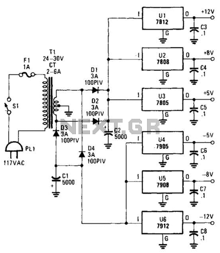
This dual-polarity, multivoltage power supply can be constructed with a minimal investment. The circuit utilizes 78XX and 79XX series voltage regulators, four 3-A diodes, a 24-30 V, 2-6 A transformer, and eight filter capacitors. The described dual-polarity, multivoltage power supply...
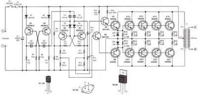
The step-up section of this inverter circuit utilizes a transformer with a 12V center-tapped (CT) secondary and a primary winding designed for 0 to 220V. The operating frequency is established by a flip-flop configured to 50 Hz. The inverter circuit...
The circuit depicted is utilized in a power supply system to promptly disconnect the power supply in the event of an over-voltage condition during either the grid's on or off phase, thereby protecting the power capacitors. This circuit serves a...
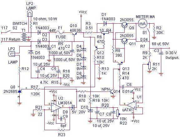
With reference to the schematic, lamp LP2 is a power-on indicator. The other lamp (lower) lights when the unit reaches its preset current limit. R5, C2, and Q10 (TO-3 case) operate as a capacitor multiplier. The 36-volt zener across...

The simple transistor tester in Figure 1 allows for the identification of the type of transistor and aids in detecting the emitter, collector, and base of the transistor. The simple transistor tester circuit is designed to facilitate the identification of...