
emergency lamp circuit problem
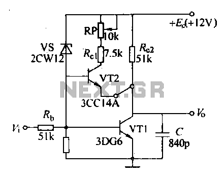
A comprehensive analysis of the circuit indicates that the Zener diode's role is critical in the overall functionality of the design. The Zener diode's breakdown voltage must align with the requirements of the circuit to ensure proper transistor activation. When selecting the transistor, consideration of the total LED current draw is essential, as this will dictate the transistor's specifications. A Darlington pair could provide the necessary gain for higher current applications, while a simpler transistor like the BC337 may suffice for lower current demands.
The LM317 voltage regulator's configuration should be optimized to ensure it operates effectively within the desired voltage range. Adjustments to R15 and R16 will directly influence the transistor's ability to turn on and maintain current flow through the LEDs. The proposed two-stage charging strategy for the battery is a practical solution to balance the need for fast charging and maintaining battery health through float charging. Implementing a memory cell will enhance the circuit's efficiency by ensuring it switches between charging modes appropriately.
In summary, the circuit requires a careful balance of component values and configurations to achieve optimal performance. The safety considerations, particularly with regards to mains voltage and sensitive components, must be prioritized in the design and implementation stages.I think the zener diode is not producing enough current on its breakdown state to turn on the transistor. I tried removing the resistor R2 but still won`t work. Can you help me how to make this work First, the zener looks like the voltage selection might be too high.
depending on the tolerance of the zener it may not regulate the o utput voltage because the drop is too high so it never conducts. This might work as long as the zener is the right voltage though. Third, T2 may have to be a higher current transistor or Darlington if the LEDs combined current draw is significant. There`s no current rating for the LEDs so it is hard to tell. And when T2 is a single transistor we`d have to see if R15 is low enough to turn it on properly. My circuit designs should be regarded as experimental. Although they work in simulation, their component values may need altering or additional components may be necessary when the circuits are built.
Due safety precautions should be taken with any circuit involving mains voltage or electrostatic-sensitive components. But as is, R15 may have to be lowered in value because the min gain of the BD140 is spec`d quite low, and i see now that the LEDs are probably EACH being driven at around 50ma, so that`s 600ma collector current roughly.
In addition to that, a resistor across the input of the LM317 is a good idea too to make sure T2 turns on fully. With R16 a lower value and VR1 adjusted all the way up, the 6v, 4. 5AHr battery might charge OK. The zener will prevent overcharging if it is sized right, but then again i would not want my battery charging all the time as many of these lights (including commercial units) do.
The battery dries up. Well, we have on the one hand the fact that we need to charge the battery with a decent amount of current to get it to charge all the way up to the max voltage, but then we need a lower voltage set point when it is time to float charge (ie keep it on standby). So we cant get away without a two stage charger i think. Stage 1 would be charging at say 400ma until it reaches the top voltage limit of the battery like with a set point of around 7.
2 volts, and then for Stage 2 lower the voltage set point to around 6. 9v for the long term float charge. This would take some sort of memory cell to acknowledge that the cell voltage had reached the max so from then on we want to only charge at the float charge level. A memory cell could be made from two small transistors or an op amp (of course a Flip Flop could be used but who wants to add that to this circuit).
Secondly, I believe the 10mm LEDS are just that. 10mm white LEDS that use only 20mA per LED. Total of 12x20Ma= 140Ma. Still good. No need for a BD of any sort. A little BC 337 can handle that for ever when saturated. First, the LM317 isnt doing much because the zener takes over, unless the zener is there just for protection in case the LM317 fails, but then if the LM317 fails then the zener wont help regulate anyway because it uses the LM317 to regulate too, thus the LM317 is barely doing anything. It makes the charge current a little more constant with a given battery voltage, but who needs that because the battery voltage varies anyway.
Second, when the battery is charged it can reach more than 7 volts. With 3v LEDs that leaves 4 volts, and the series resistors are 100 ohms, so 4/100=40ma each LED, and 40ma each times 12 is 480ma total through the transistor. Not a real lot, but i`d want a decent transistor there. Maybe smaller would work though it`s up to you to try. It appears that you have the output of the LM317 adjusted for 6. 8 volts. I dont think that`s enough because the battery will charge up to 7. 2 volts when fully charged. Realize also that if the output of the LM317 is adjusted for 7. 2 volts, then when the battery is 7. 1 volts you`ll only get 0. 1/16=0. 00625 amps of current, not nearly enough for a good quality Lead Acid bat 🔗 External reference
Related Circuits
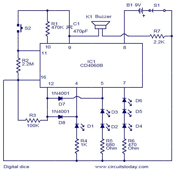
This is a simple and easy-to-construct digital dice circuit. The circuit is based on a single IC, CD4060B. The dice consists of six LEDs marked D1 to D6. The number of LEDs glowing indicates the numeral. The heart of...

The add-on circuit presented here is useful for stereo systems. This circuit has provisions for connecting stereo outputs from four different sources or channels as inputs, with only one of them selected and connected to the output at any...
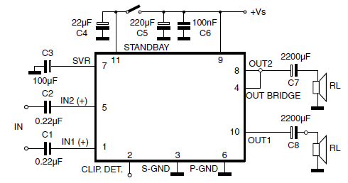
The car radio application utilizes a Class AB Audio Power Amplifier, typically featuring the TDA7360 IC. This amplifier provides 22W output in either bridge or stereo configuration and includes several beneficial features such as a minimal requirement for external...
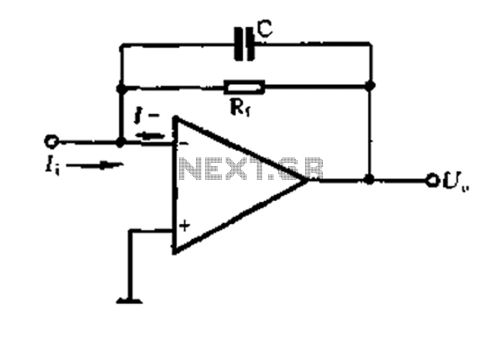
A current-voltage conversion circuit. A current-voltage conversion circuit is designed to transform an input current signal into a corresponding voltage signal. This type of circuit is fundamental in various applications, including sensor interfacing, signal conditioning, and analog-to-digital conversion processes. Typically,...
The purpose of this circuit is to animate shop windows using a capacitive sensor positioned behind a postcard-like banner. The card is placed against the glass inside the shop window, allowing visitors to activate the relay by placing their...
Various sawtooth voltage generators utilize the principle of capacitor charging and discharging to produce sawtooth waveforms in both forward and reverse directions. A simple sawtooth voltage generator circuit is straightforward in design; however, it suffers from poor linearity in...
Warning: include(partials/cookie-banner.php): Failed to open stream: Permission denied in /var/www/html/nextgr/view-circuit.php on line 713
Warning: include(): Failed opening 'partials/cookie-banner.php' for inclusion (include_path='.:/usr/share/php') in /var/www/html/nextgr/view-circuit.php on line 713