Encoder-decoder

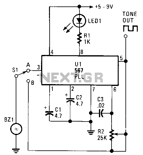
The transducer circuit can function as either a tone encoder or decoder by adjusting the position of switch Sl. The operating frequency of this dual-purpose circuit is set by capacitors C3 and resistor R2. Capacitors C1 and C2 are not critical and can have values ranging from 1 to 5 microfarads. When the circuit receives an on-frequency signal, LED1 will illuminate. Although a two-wire piezo transducer with a resonance frequency of 2500 Hz was utilized in this circuit, any piezo unit can be employed, provided that C3 and R2 are selected to match the transducer's operating frequency. With power applied and switch Sl in the B position, R2 should be adjusted for the loudest tone output, tuning the circuit to the resonance frequency of the transducer. In this configuration, the circuit operates as an acoustical or tone signal encoder. By switching to the A position and directing an on-frequency audible tone towards the transducer, the LED should light up, indicating successful signal decoding.
The transducer circuit described serves a dual role, functioning as both a tone encoder and decoder, depending on the configuration of switch Sl. The selection of switch position directly influences the operational mode of the circuit. In encoder mode (position B), the circuit generates audio tones, with the frequency determined by the combination of capacitor C3 and resistor R2. Proper tuning is critical; thus, R2 must be adjusted to achieve the maximum output at the transducer's resonance frequency, which is particularly important for effective sound production.
Capacitors C1 and C2 play a supporting role in the circuit's operation, allowing flexibility in their values without significantly affecting performance. This adaptability provides ease of sourcing components, as values between 1 and 5 microfarads are acceptable for these capacitors.
When the circuit is switched to decoder mode (position A), it becomes sensitive to incoming audio signals. The circuit is designed to detect specific frequencies, and when an on-frequency tone is received, LED1 serves as an indicator of successful signal detection, illuminating to confirm that the circuit has accurately decoded the incoming signal. This feature is particularly useful in applications requiring tone detection or signal processing.
Overall, the circuit's design emphasizes versatility and ease of use, allowing for straightforward switching between encoding and decoding functions while ensuring reliable performance across a range of piezo transducer types, as long as the frequency tuning components are appropriately selected.The transducer circuit can be operated as either a tone encoder or decoder by changing the position of Sl. The operating frequency of that dual-purpose circuit is determined by C3 and R2. Capacitors Cl and C2 are not critical and can be of almost any value between 1 and 5 mf. When the circuit is receiving an on-frequency signal, LEDl lights. Although a two wire piezo transducer with a resonance frequency of 2500 Hz was used in the circuit, any piezo unit should work-as long as the values of C3 and R2 are selected to tune to the transducer"s operating frequency.
With power on and Sl in the B position, adjust R2 for the loudest tone output. The circuit should be tuned to the resonance frequency of the transducer. In that position, the circuit can be used as an acoustical or tone signal encoder. Next, switch to the A position and aim an on-frequency audible tone toward the transducer; the LED should light, indicating a decoded signal.