
ESR-Meter
Two versions are provided. The first version is based on the original schematics, with the modification of replacing SMD capacitors with standard through-hole capacitors. The second version features some modifications, including the removal of the transformer and the addition of a standard DC jack. Additionally, the PIC and display headers are positioned far enough from other components to allow adequate space for the display on the PCB. Both versions include pads for 27mm and 22mm capacitors (4.7µF). Review the designs and feel free to make any necessary modifications. They can be shared on a website for others who may find them useful.
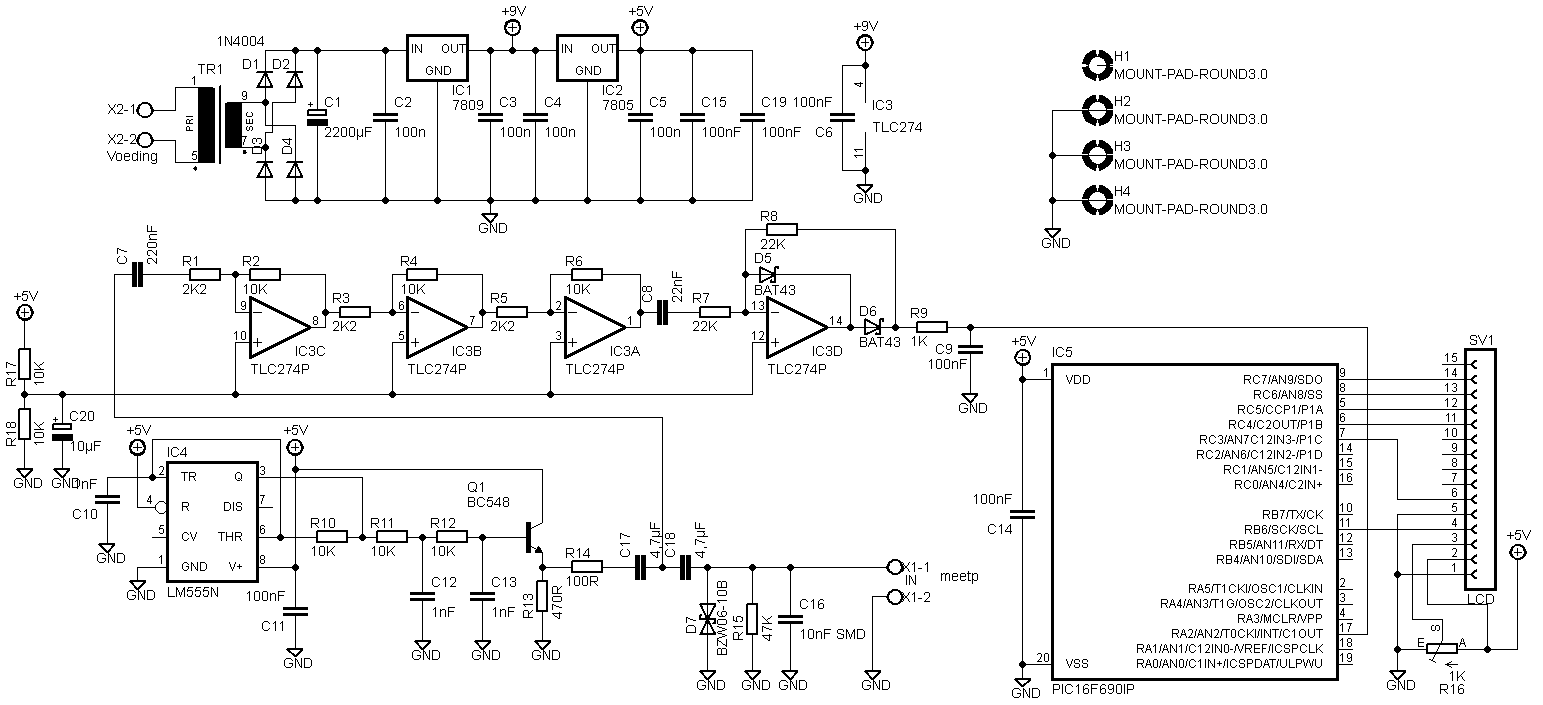
The circuit design includes two distinct versions aimed at improving usability and component accessibility. The first version retains the core schematic while substituting surface-mount device (SMD) capacitors with standard through-hole capacitors. This change enhances the ease of assembly and repair, as through-hole components are generally simpler to handle and solder, especially in prototyping scenarios.
The second version introduces further modifications by eliminating the transformer, which simplifies the power supply requirements and reduces the overall size of the circuit. The incorporation of a standard DC jack allows for straightforward power connections, making it more user-friendly for integration into various projects. The design also strategically places the PIC microcontroller and display headers at a distance from other circuit elements. This arrangement not only facilitates easier connections to the display module but also minimizes potential interference, ensuring reliable operation.
Both designs feature pads for 27mm and 22mm capacitors rated at 4.7µF, which provide flexibility in selecting suitable capacitors for different applications. The inclusion of these pads allows for customization based on specific needs or preferences, thereby enhancing the versatility of the circuit.
Overall, these versions of the circuit schematic are designed to be practical and adaptable, catering to a wide range of applications while maintaining ease of use and assembly. The modifications made in both versions aim to optimize performance and accessibility for users, making these designs valuable resources for electronics enthusiasts and professionals alike.2 versions. First is one based on your schematics, except that I`ve changed those smd capacitors for standard through hole ones. Second one is somewhat modified. I`ve excluded transformer and put in standard dc jack. Also, pic and display header are located so far away from other stuff so that there is enough place for display to be on the p
cb. Also, you`ll see that, on both versions I`ve also put pads for 27 and 22mm capacitors (4. 7uF). Check it out and feel free to make any modifications you think are necessary. You can put it on your website if you like, maybe someone will find it useful 🔗 External reference