
Expanded-scale-analog-meter
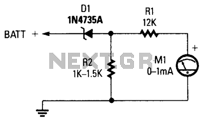
The circuit comprises a 0-1 mA meter (M1), a 6.2 V zener diode (D1), and a 12 kΩ, 1% resistor (R1). A load resistor (R2) is included in the circuit for the zener diode, with a non-critical value ranging from 1000 to 1500 Ω. The meter is capable of reading voltages from 6 to 18 volts, making it suitable for testing a car's charging system.
The circuit functions as a voltage measurement tool, utilizing the zener diode to provide a stable reference voltage. The 6.2 V zener diode (D1) is critical for maintaining a consistent output voltage, ensuring that the meter (M1) can accurately reflect the input voltage within the specified range of 6 to 18 volts.
The primary role of the resistor R1, rated at 12 kΩ with a tolerance of 1%, is to limit the current flowing through the zener diode, thereby protecting it from excessive current that could lead to damage. The choice of a 12 kΩ resistor helps to establish a suitable operating point for the zener diode, ensuring its proper function as a voltage regulator.
The load resistor R2, which can vary between 1000 to 1500 Ω, serves to provide a path for the current when the zener diode is in operation. While its exact value is not critical, selecting a resistor within this range ensures that the zener diode operates effectively without drawing excessive current, thus maintaining the integrity of the voltage reference.
The meter (M1) is calibrated to display voltages between 6 to 18 volts, which is particularly advantageous for automotive applications. This range is ideal for monitoring the charging system of a vehicle, allowing for the assessment of the alternator's output and the overall health of the battery. By connecting this circuit to the vehicle’s electrical system, users can quickly ascertain whether the charging voltage is within acceptable limits, aiding in troubleshooting and maintenance tasks.
Overall, this circuit is a practical solution for automotive technicians and hobbyists alike, providing a reliable means of measuring voltage in a straightforward and efficient manner.The circuit consists of 0-1 mA meter M1, 6.2-V zener diode D1, and 12-KO, 1 % resistor Rl. R2 is included in the circuit as a load resistor for the zener diode. The value of R2 isn"t critical; use a value of 1000 to 1500 0. The meter reads from 6 to 18 volts, which is perfect for checking a car"s charging system. 🔗 External reference