
Field circuit diagram of the needle
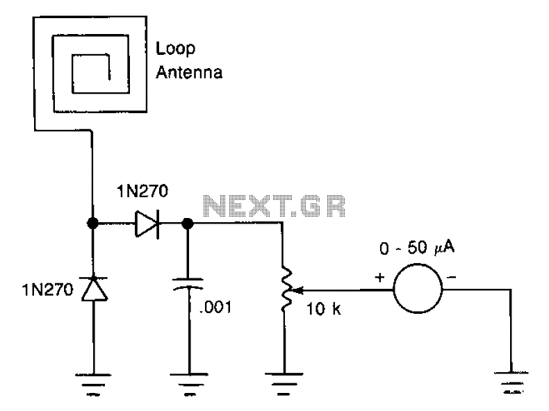
The described antenna design incorporates a compact configuration that facilitates RF signal reception and processing. The 20 cm insulated strands serve as the primary radiating element, effectively capturing radio frequency signals. The use of strands allows for flexibility in the antenna's design, which can be advantageous in various applications where space is limited.
The small plastic enclosure not only protects the antenna elements from environmental factors but also aids in maintaining the structural integrity of the assembly. The integration of two diode rectifiers is crucial for converting the received RF signals into a usable direct current (DC) output. This rectification process is essential for applications that require the conversion of RF energy into a form that can be utilized for further processing or measurement.
The inclusion of a 10k potentiometer allows for the adjustment of the signal level, effectively functioning as a variable attenuator. By modifying the resistance, users can control the amplitude of the signal being processed. This feature is particularly useful in applications where signal strength may vary, enabling optimal performance and preventing signal overload.
Overall, this antenna design presents a versatile solution for RF signal reception, with its compact form factor, protective housing, and adjustable signal processing capabilities. Such characteristics make it suitable for a wide range of electronic applications, from basic RF experiments to more complex communication systems.Antenna is about 20cm of insulation made of strands, these strands glued around inside a small plastic box. RF current by two diode rectifier, a 10k potentiometer to pin field provides a variable attenuator.
Related Circuits
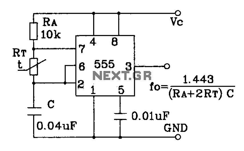
The circuit utilizes a 555 timer configured as a multivibrator, where the oscillation frequency is determined by resistors R1, R2, and capacitor C1. The frequency formula is given by fo = 1.443 / ((R1 + R2) * C1). The...
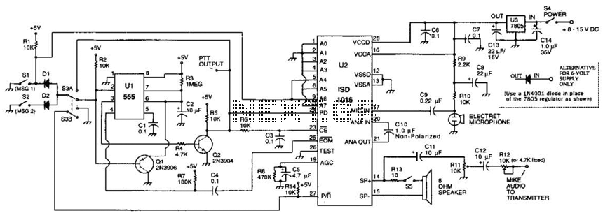
The circuit utilizes an ISD1016 audio record/playback chip from Information Storage Devices, Inc. to record and playback messages on demand. While it is primarily designed for use with transmitters, it can also serve as an electronic notepad or similar...
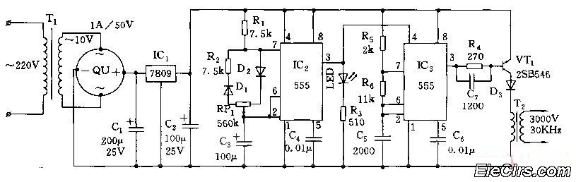
Adjust the RP1 to modify the pulse duty cycle of IC2, which in turn alters the pulse oscillation time of IC3. This regulation allows for the control of ozone generation time, effectively changing the concentration of ozone in the...
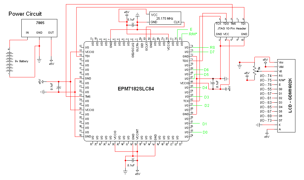
The schematic for this project is a modified version of the CPLD development board schematic. Several new components have been added for this project, and the completed schematic is presented below. The primary components in the schematic include the...
555 precision temperature sensor with temperature frequency converting circuit diagram consisting of: The 555 precision temperature sensor operates by converting temperature variations into frequency signals. This circuit typically utilizes a 555 timer IC configured in astable mode to generate...
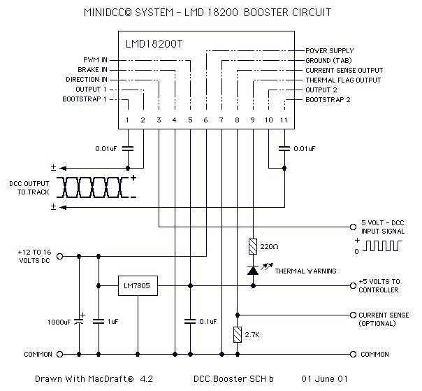
This page features H-Bridge circuits used for controlling direct current motors. Several designs are shown using both CMOS and Bi-Polar power devices. These circuits could be used as the basis for Model Railroad DCC Boosters or PWM motor controllers....
Warning: include(partials/cookie-banner.php): Failed to open stream: Permission denied in /var/www/html/nextgr/view-circuit.php on line 713
Warning: include(): Failed opening 'partials/cookie-banner.php' for inclusion (include_path='.:/usr/share/php') in /var/www/html/nextgr/view-circuit.php on line 713