
Five-step voltage-level indicator
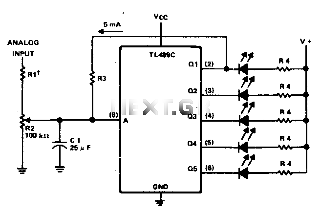
The circuit utilizes a high-impedance operational amplifier configured as a voltage follower to ensure minimal loading on the input signal. The output from the op-amp feeds into a comparator circuit, which compares the input voltage against predefined reference levels corresponding to each LED in the array. The reference voltages can be set using a resistor divider network connected to a stable reference voltage source.
When the input voltage reaches specific thresholds, the comparator outputs transition, activating the open-collector outputs. These outputs are connected to the anodes of the LEDs, while the cathodes are tied to ground through current-limiting resistors. This configuration allows the circuit to illuminate the appropriate number of LEDs based on the input voltage level, providing a clear visual indication.
To ensure the circuit operates correctly, it is crucial to maintain the input voltage within the specified range. If the input voltage exceeds eight volts, it may lead to undesired behavior or damage to the components. Therefore, voltage clamping devices such as Zener diodes may be incorporated to protect the input stage from overvoltage conditions.
In summary, this circuit effectively visualizes analog voltage levels through a straightforward LED array, combining high input impedance, open-collector outputs, and adjustable reference voltages to create an intuitive and informative display.This circuit provides a visual indication of the input analog voltage level. It has a high input impedance at pin 8 and open-collector outputs capable of sinking up to 40 milliam-peres. It is suitable for driving a linear array of 5 LEDs to indicate the level is 5 steps The voltage at the analog input should be in the range of zero to approximately one volt and should never exceed eight volts. 🔗 External reference
Related Circuits
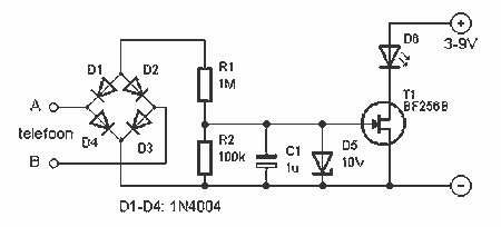
This indicator shows whether the phone is busy or not. When the line is busy, LED D6 is off. The line voltage at points A and B is attached. By the rectifier bridge behind the connection, the polarity does...
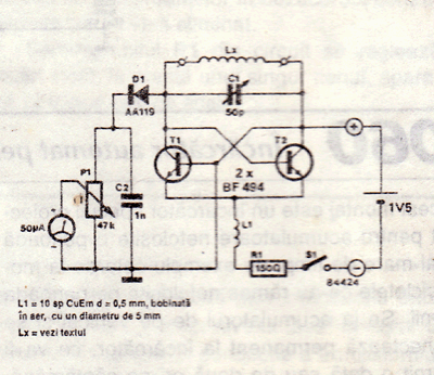
A UHF indicator, or wavemeter, is a device that measures frequencies and determines the resonance frequency of an LC circuit. This device operates without the need for radiation. The oscillator is constructed using transistors T1 and T2 (two BF494),...
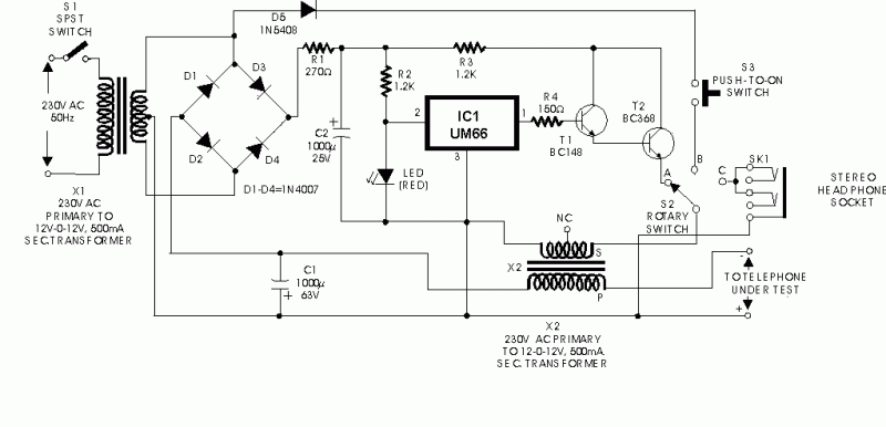
Here is a circuit of an offline telephone tester which does not require any telephone line for testing a telephone instrument. The circuit is so simple that it can be easily assembled even by a novice having very little...

This indicator senses the switching on and off of the 48-V DC line voltage and transmits the pulses to logic circuitry. An Hl1A10 threshold coupler, with capacitor filtering, creates a straightforward circuit that can provide dial pulse indication while...
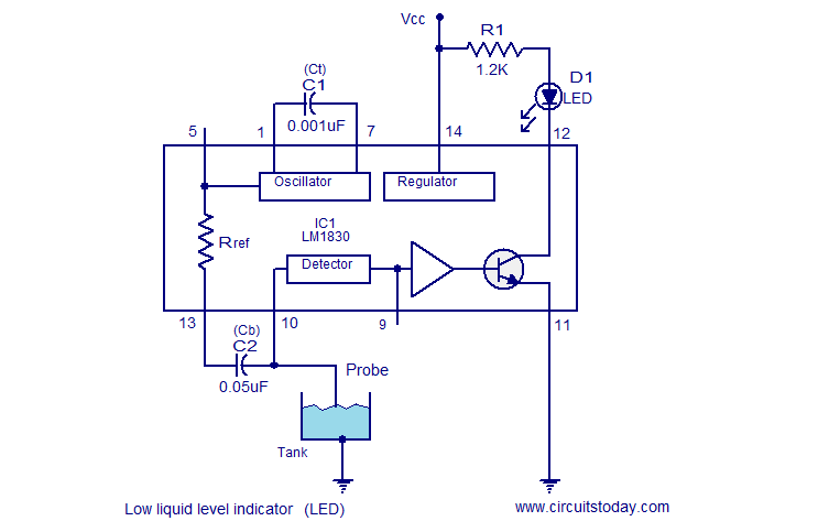
The following circuit illustrates a Liquid Level Sensor Indicator Circuit utilizing the LM1830 integrated circuit. Features: Manufactured by National Semiconductors, the device... The Liquid Level Sensor Indicator Circuit employing the LM1830 IC is designed to detect and indicate the level...
A battery-status indicator circuit is useful for monitoring portable test equipment and similar devices. LED D1 flashes to attract the user's attention, signaling that the circuit is operational, preventing it from being left on unintentionally. The circuit produces approximately...
Warning: include(partials/cookie-banner.php): Failed to open stream: Permission denied in /var/www/html/nextgr/view-circuit.php on line 713
Warning: include(): Failed opening 'partials/cookie-banner.php' for inclusion (include_path='.:/usr/share/php') in /var/www/html/nextgr/view-circuit.php on line 713