
Flash-meter
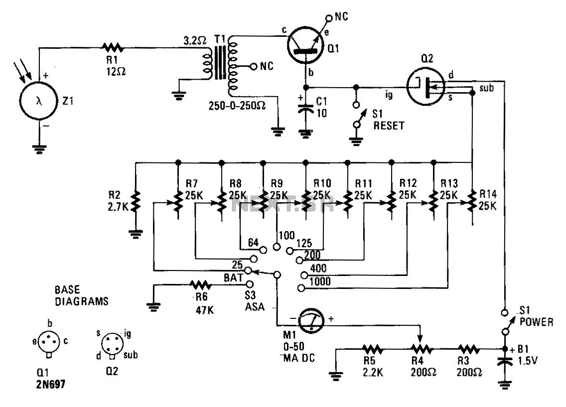
The circuit comprises an insulated-gate field-effect transistor (IGFET) labeled Q2 and a silicon photo cell designated Z1. Transformer T1, an audio-output type, is configured in reverse within the circuit. When a sudden flash from a photoflash unit is detected by Z1, it generates a voltage pulse that travels through the low-impedance winding of T1 via resistor R1. This voltage pulse is then stepped up in the primary winding of T1, which has a resistance of 500 ohms, before being rectified by transistor Q1. Q1 is repurposed as a diode by having its emitter lead removed close to the case. Consequently, Q1 charges capacitor C1 to a voltage level that is proportional to the amplitude of the electrical pulse produced by the light from the flash unit.
Capacitor C1 regulates the current flowing through Q2, which features a very high input impedance. The current through Q2 is measured by meter M1, a direct current unit with a range of 0-50 microamperes, calibrated in f-stops. The exceptionally high internal resistances of both Q1 and Q2 allow C1 to maintain its charge for several minutes, providing ample time to take a reading from M1. The charge on C1 can be discharged to ground and reset to 0 V by pressing reset button S1, preparing the flashmate for the next photoflash. Trim potentiometers R7 through R14 are adjusted to specific values to ensure accurate readings corresponding to various film sensitivities or exposure indexes.
The described circuit operates effectively as a light intensity measurement device, utilizing the properties of IGFETs and photodetection to provide precise readings for photographic exposure settings. The unique configuration of the transformer allows for voltage amplification necessary to drive the rectification process, while the use of a modified transistor as a diode enhances the efficiency of charge accumulation in the capacitor. The calibration of the meter in f-stops ensures that users can directly relate the readings to photographic exposure requirements, making this circuit particularly useful for photographers seeking to optimize their settings based on ambient light conditions. The inclusion of trim potentiometers adds versatility, allowing for adjustments based on different film types or sensitivity ratings, ensuring that the device can cater to a broad range of photographic applications.Insulated-gate, field-effect transistor (IGFET), Q2 and silicon photo cell Zl form the heart of this circuit. Transformer T1 is an audio-output type, but it"s reversed in the circuit. A sudden flash from a photoflash unit detected by Zl sends a voltage pulse through the low-impedance winding of Tl via Rl.
That voltage pulse is stepped-up in Tl"s 500-!l, primary winding before being rectified by Ql. Transistor Ql is used as a diode; its emitter lead was snipped off close to the case. Ql then charges Cl to a value proportional to the amplitude of the electrical pulse generated by the light from a flash unit. Capacitor Cl controls the current flowing through Q2, which has a very high-input impedance. The current through Q2 is read by meter Ml, a 0-50 p.A de unit, which has been calibrated in f-stops. The extremely high internal resistances of Ql and Q2 will allow Cl to retain its charge for several minutes; this is more than enough time for you to take your reading of Ml.
The charge on Cl is shorted to ground and returned to 0 V by depressing reset button Sl. The flashmate is ready to read the next photoflash. Trim potentiometers, R7 through Rl4, are.adjusted to values which will yield correct readings for corresponding film sensitivities, or exposure indexes. 🔗 External reference