
Flashing Heart circuit diagram

The circuit described involves a combination of Red, Yellow, and Green LEDs, each with distinct operational characteristics. The Red LEDs are configured to flash in unison, creating a visually striking effect that can be utilized for various signaling applications. The Yellow LEDs, designed to illuminate alternately, provide a unique pattern that can be employed for decorative or alert purposes. The continuous illumination of the Green LEDs serves as an indicator that the circuit is powered and operational.
The adjustable flash rate of the Red and Yellow LEDs is controlled by resistor R9. This resistor can be replaced with a potentiometer to allow for variable adjustment, enabling users to customize the flashing speed to suit their preferences or project requirements. The board layout includes provisions for soldering a fixed value resistor in place of R9, offering flexibility in circuit design.
In terms of physical design, the circuit board features an area designated for a photograph, which can enhance the aesthetic appeal of the project. A custom frame can be constructed to encase the circuit board, providing both protection and a polished appearance. This design consideration allows for creative expression while maintaining the functionality of the electronic components. Overall, this circuit presents a versatile solution for both visual signaling and decorative purposes.Once power has been applied to the circuit, the Red LEDs should all be flashing on and off together. The Yellow LEDs should be flashing on and off, but only every other Yellow LED should be on at one time. The Green LEDs will stay on at all times. The flash rate can be adjusted by turning R9. Connections for a fixed value resistor for R9 are provi ded on the board layout if preferred. To dress up the project, a favorite photograph can be placed in the heart, and a frame can be made to fit the circuit board. 🔗 External reference
Related Circuits
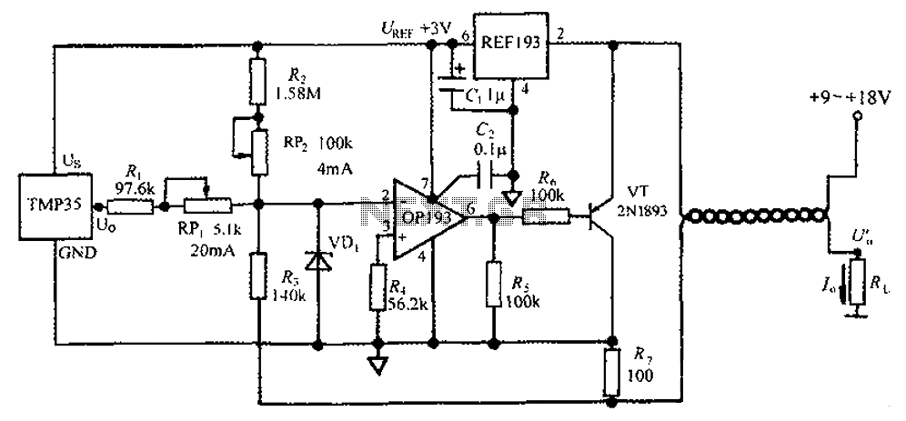
The circuit consists of a TMP35 temperature transmitter that converts a voltage signal output from the TMP35 into a standard 4 to 20 mA current signal. This configuration is suitable for use in automated instrumentation and industrial temperature control...
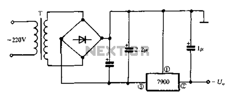
7900 series three-terminal fixed negative output voltage regulator circuit The 7900 series comprises a range of three-terminal fixed negative voltage regulators designed to provide stable output voltages. These regulators are specifically engineered to deliver a consistent output voltage, which is...

The TN-1 Intelligent Negative Pulse Charging Circuit is a sophisticated device designed for efficient battery charging. It operates as a half-bridge charger, which is a common configuration in such circuits. The negative pulse charging mechanism is facilitated by a...

The ESR Meter is essentially an AC Ohmmeter equipped with specialized scales and protective circuitry. It provides continuous readings of series resistance in electrolytic capacitors. Operating at 100 kHz, it maintains the capacitive reactance factor close to zero. The...

This circuit offers an advantage over traditional continuity testing devices, which typically utilize a multimeter to assess circuit continuity. Multimeters are not suitable for testing high impedance or resistance circuits, such as transformers, capacitors, and high-value resistors. This circuit...

The circuit diagram illustrates a group of four analog electronic circuit switches (S1 to S4). Switches S1, S2, and S3 are utilized in a parallel delay circuit. When the power is activated, resistor R4 drives the triac VT, which...