
Flashing light indicates the light switch circuit
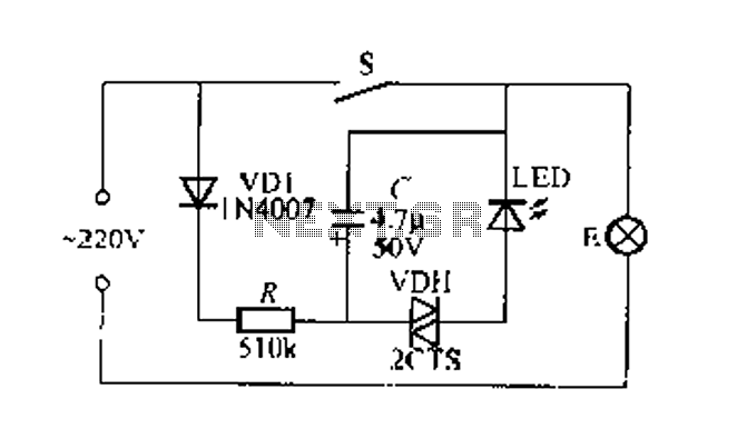
The circuit operates on the principle of providing a visual indication of the operational status of a lighting system. The primary component, the switch S, controls the flow of current through the circuit. When S is closed, the circuit is energized, allowing lamp E to light up, indicating normal operation. The inclusion of the rectifier diode VD1 ensures that the AC voltage is converted to a suitable form for charging capacitor C, which stores energy for the oscillation process.
Resistor R plays a crucial role in limiting the current that charges capacitor C, preventing damage to the components and ensuring stable operation. The relaxation oscillator is formed by the interaction between capacitor C and the bidirectional trigger diode VDH. As the capacitor charges and discharges, it creates a pulsing effect that causes the LED (light-emitting diode) to flash. The flashing light serves as an effective indicator, especially in low-light conditions, allowing users to easily identify the switch's location.
In the event of a power outage, if switch S is activated and the LED does not light up, this indicates that the main bulb E has failed, thereby alerting the user to check the bulb. The VDH diode is selected for its ability to trigger at a specific voltage range, making it suitable for this application. The use of a high-brightness red LED ensures maximum visibility, enhancing the overall functionality of the circuit. This design is particularly useful in residential and commercial settings, where reliable indicators of power status are essential for safety and convenience.Figure 2 foot emitting a flashing light switch circuit indication. when s is closed, normal light E lights flashing hair light indicates power loss of power does not work shoes . Open after s. 220V AC by lamp E and a rectifier diode VD1, R buck limit the flow of the charging capacitor c. Negative zoot Sui and capacitance C of the present circuit utilizes two-way trigger diode VDH of charge and discharge principle can constitute a relaxation oscillator, so luminous tube I, ED will flashing light at night is very eye-catching, makes it easy to find switch position. If s beat Ji, LED small light, not the light bulb filament E blown, it is a power outage. VDH may be a turning point in the voltage range of 20-40V bidirectional trigger diodes as 2CTSIA, DB3 type.
I.ED most tincture high-brightness red light emitting diodes.
Related Circuits
This circuit is designed for the selection of alternative sources. It integrates mechanical selection through a rotating switch S1, electronic control of relays RL1 to RL10, and optical indication of the selection via the display DSP1. The circuit operates by...
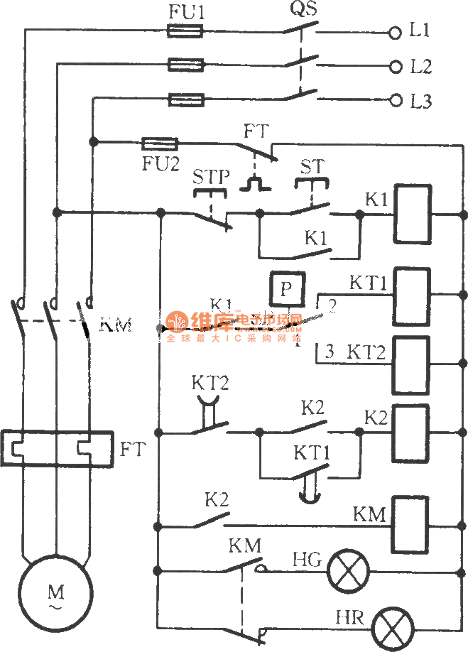
The circuit utilizes two time relays, KT1 and KT2, which are connected in series with the contacts of an electric contact pressure gauge (SP). This configuration helps to mitigate issues such as tremors or sparking that may occur due...

The schematic for this project is not overly complex; however, it is crucial to understand the circuit board and its operation due to the high voltages generated. Below is a rough draft schematic of the camera used for this...
The Clapp oscillator is a type of electronic oscillator constructed from a transistor or vacuum tube and a positive feedback network. The Meissner oscillator circuit is a harmonic oscillator that consists of an active electronic element, such as a...
This characterization circuit, along with a PC and specific software, accurately measures the complete discharge cycle of a rechargeable AA cell. The capacity and output resistance of the cell can be easily determined from the resulting curve of these...
The remote control electric hoist control circuit comprises a wireless transmitter, a wireless receiver control circuit, and a main control circuit. The wireless transmitter utilizes the TWH9326 four-key BP transmitter. The wireless receiver control circuit includes a power supply...
Warning: include(partials/cookie-banner.php): Failed to open stream: Permission denied in /var/www/html/nextgr/view-circuit.php on line 713
Warning: include(): Failed opening 'partials/cookie-banner.php' for inclusion (include_path='.:/usr/share/php') in /var/www/html/nextgr/view-circuit.php on line 713