
Flashing Light with Triacs
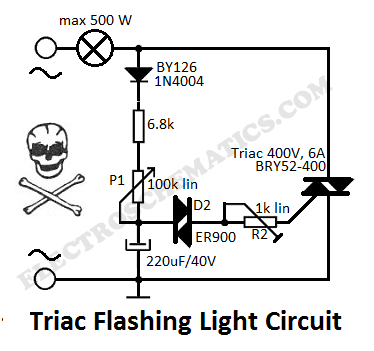
The flashing light circuit is designed to create a visual indication through intermittent illumination, which can be adjusted in frequency to suit various applications. At the core of the circuit are triacs, which are semiconductor devices capable of controlling power. They allow the circuit to switch on and off rapidly, producing the desired flashing effect.
The D1 diode serves a critical function in this circuit by providing rectification, ensuring that the current flows in a single direction. This is essential for the proper operation of the triacs, as they require a specific polarity to function effectively. The semi-adjustable resistor, often a potentiometer, allows for fine-tuning of the circuit's frequency. By adjusting this resistor, the user can change the amount of current flowing through the circuit, thereby altering the flashing rate of the light.
The circuit may also include additional components such as capacitors or resistors to stabilize the operation and enhance performance. Capacitors can be used to filter out noise and provide a smoother operation, while resistors can limit current to protect sensitive components.
In summary, this circuit is a versatile solution for creating variable frequency flashing lights, suitable for applications ranging from decorative lighting to signaling devices. The use of triacs, along with the diode and adjustable resistor, ensures efficient operation and customization of the flashing frequency.This flashing light circuit uses triacs to generate an intermittent light with variable frequency. Additional components are the D1 diode and semi adjustab.. 🔗 External reference
Related Circuits
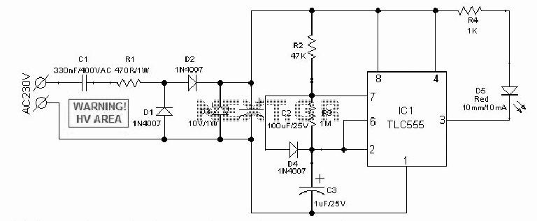
An AC mains operated single LED flasher circuit is designed using the widely used CMOS timer chip TLC555. The entire circuit is powered directly by the grid supply of 230VAC through a capacitive potential divider and associated components. This LED...
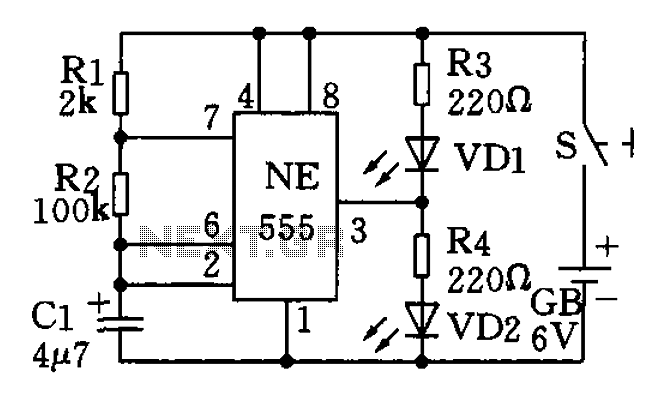
The circuit utilizes a 555 timer as the central component of a flashing light circuit. In normal operation, the light-emitting diodes (LEDs) VD1 and VD2 alternate flashing. The circuit comprises the NE555 timer, resistors R1 and R2, and capacitor...
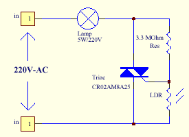
The series of light switches is slightly different from traditional designs. These light switches can operate directly on the AC power network. The main components of the circuit include a TRIAC and a Light Dependent Resistor (LDR). The circuit...
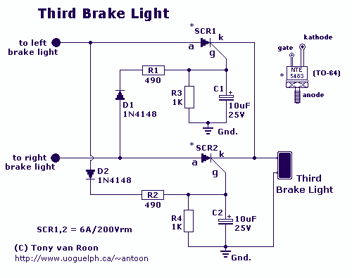
What's so special about this circuit? Well, the first third-brake light I installed I had to pull a wire from the Third Brake Light all the way underneath the carpet to the brake-pedal-switch and I thought it would be...
This circuit is relatively simple yet valuable, as it offers a high-quality interior light delay feature. The circuit for the interior light delay is designed to control the duration for which the interior lights remain illuminated after a door is...
The principle is that the resistance of metals increases at higher temperatures, and a heated wire suspended in a gas will lose heat by conduction and convection in proportion to the number of gas molecules present; thus, the heat...
Warning: include(partials/cookie-banner.php): Failed to open stream: Permission denied in /var/www/html/nextgr/view-circuit.php on line 713
Warning: include(): Failed opening 'partials/cookie-banner.php' for inclusion (include_path='.:/usr/share/php') in /var/www/html/nextgr/view-circuit.php on line 713