
flashingLEDs
Several individuals have requested clarification on calculating resistor values for a triac circuit. This information may be beneficial for adapting the Sous Vader for custom builds. The circuit in question involves the resistor values R1 and R2 in an optoisolator, triac, and mains configuration. Initially, R1 was incorrectly listed as 10kΩ, but the correct value used is 1kΩ, which works but could be improved. R1's purpose is to limit the current into the LED side of the optocoupler, ensuring that the LED current exceeds the maximum "IFT" value specified in the datasheet, which is 5mA for the MOC3023. With a typical LED voltage drop of 1.2V and a 5V control line, R1 should be chosen carefully to avoid excessive current draw from the microcontroller. In future builds, a value of 680Ω will be used. R2, which also has a value of 680Ω, serves to limit the current through the switch side of the optocoupler while providing sufficient current to the triac gate to activate it. The current limit for the MOC3023 is 1A, and calculations indicate that a 680Ω resistor with 240V mains results in a peak current of 500mA, which is within safe limits. The lowest value of R2 that maintains the 1A limit is 340Ω. The gate threshold current for the Q4025 triac is 80mA, and the mains AC voltage required to reach this current is calculated. Although the 680Ω resistor requires 10.1° to trigger the triac, this results in a minimal power loss of about 99.2% of full power. Measurements indicate that the voltage across R2 rises until a critical value is reached, switching on the triac and dropping the voltage to nearly zero. The triac switches at 14V, corresponding to a gate current of approximately 12mA, which is acceptable as the typical threshold current can be lower than the maximum. For the power rating of R2, conservative estimates suggest using the higher threshold current of 80mA, resulting in a duty cycle of 5.6%.
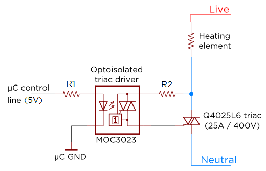
The circuit under discussion utilizes a triac in conjunction with an optoisolator to control AC loads. The optoisolator, specifically the MOC3023, plays a crucial role in ensuring electrical isolation between the control circuit and the high-voltage AC circuit. Resistor R1 is strategically placed to limit the forward current through the optocoupler's LED, ensuring that the LED operates within its safe limits while providing adequate current to trigger the phototransistor on the output side. The selection of R1 is critical; it must be low enough to ensure that the LED current exceeds the IFT (forward current threshold) specified in the MOC3023 datasheet, yet high enough to prevent excessive current draw from the controlling microcontroller, which could lead to damage or reduced lifespan.
On the output side, R2 is positioned to limit the current flowing into the gate of the triac, ensuring that the gate current reaches the necessary threshold to activate the triac without exceeding its maximum ratings. The relationship between the AC voltage, the resistor values, and the gate current is essential for reliable operation. The calculated peak current through R2, based on a 240V AC supply, confirms that the circuit operates within safe limits, allowing for effective switching of the triac.
The triggering characteristics of the triac are also noteworthy. Although the design anticipates a gate current of 80mA to guarantee activation, real-world measurements indicate that the triac is triggered at a significantly lower gate current of approximately 12mA. This indicates that the triac is more sensitive than initially expected, which can be advantageous in terms of power efficiency and response time.
Finally, the power rating for R2 must be considered to ensure reliability under continuous operation. By conservatively estimating the power dissipation based on the maximum expected current, the design can accommodate variations and ensure long-term stability. The calculated duty cycle of 5.6% reflects the operational characteristics of the circuit, providing insights into the overall efficiency and performance of the triac control system.A few people have requested some clarification about calculating resistor values for the triac circuit. If I`m doing this correctly it might prove helpful in adapting the Sous Vader for custom builds. If I`m wrong, hopefully somebody will point out my mistake(s). Win win, right The circuit in question is reproduced below, and we`re going to talk about the size of R1 and R2 for this particular optoisolator+triac+mains configuration. It should be straightforward to adapt this discussion to 120V mains or to a different set of components. When I first put the page up, I incorrectly listed R1 as 10kΩ. I`ve actually been using 1k ©, which certainly works but as we`re about to see could be improved. The purpose of R1 is to limit the current going into the LED side of the optocoupler. To absolutely guarantee you turn it on, the LED current should be greater than the maximum value of "IFT" as quoted in the datasheet.
For the MOC3023, this is 5mA. Given a typical voltage drop across the LED of 1. 2V, and assuming you`re using a 5V control line, R1 should ideally be: We should choose R1 to be no larger than this, but at the same time it`s not good to go too small - your microcontroller might not like sourcing tens of mA, and it will decrease the life of the LED. In future builds I`ll be using 680Ω. There was no error on the other side, I`ve definitely been using 680Ω. This resistor serves two purposes. It limits the current through the `switch` side of the optocoupler to a safe value, while at the same time allowing enough current into the triac gate to switch it on.
From the Fairchild datasheet, the current limit for the MOC3023 ("ITSM") is 1A. The peak current I can expect from 240V mains through a 680ohm resistor is (240V*1. 414)/680 © = 500mA, so we`re safe. The lowest value of R2 I could use while respecting that 1A limit is 340Ω. What about triggering the triac The gate threshold current for the Q4025 triac (Littelfuse datasheet) is 80mA. This current value will be reached when the mains AC voltage reaches a value of: So the question is: how much power am I not using because my 680 © resistor takes 10.
1 ° to trigger the triac Not much: 99. 2% of full power (99. 8% with 340 ©). Teccor`s AN1003 has a nice plot that will tell you this, but to calculate it yourself you just integrate the waveform over the region where the triac is turned on. Skipping some steps, in the present case that will lead to: Theory is all well and good, but we should also measure the circuit to see if it`s respecting our calculations.
In Figure 2 we`re watching the voltage across R2 at the start of a mains halfwave. It rises from zero, then at some critical value the current is enough to switch on the triac. This essentially shorts the resistor, and the voltage drops to nearly zero. Interestingly, the switch is happening at only 14V, not the 60V we expected. If anything this is welcome, since we`re switching faster than we thought and hence getting slightly more power through. But 14V on our 680 © R2 corresponds to a gate current of only about 12mA, not the 80mA we planned for - is this reasonable Indeed it is.
Remember that 80mA was the gate current required to guarantee the triac turned on. It`s a good idea to base your plans around this value, but if you read a few triac datasheets you`ll see that the typical threshold current can be substantially less than the maximum. Lastly, what about the power rating for R2 Let`s make life easy for ourselves and be wildly conservative with our estimates.
Ignore the fact that our measurements came in lower, and take the larger value for threshold current of 80mA. For simplicity, assume also that R2 passes this current the whole time it`s turning on the triac (rather than ramping up to this value).
This represents 10. 1 ° in each 180 ° halfwave, or equivalently a duty cycle of 5. 6%. 🔗 External reference