
Flashlight circuit diagram of a motor control model

The circuit utilizes two photocells, PC1 and PC2, to control the operation of a motor based on light detection. In a dark environment, both PC1 and PC2 have high resistance, which keeps the transistors Q1 and Q2 in an off state. As a result, the relay contacts K1 and K2 remain open, preventing current flow from battery B3 through the potentiometer Rs to the motor circuit. The configuration ensures that the motor remains stationary as there is no current flow through resistor R3, which is part of the series circuit controlling relay K3.
Upon exposure to light from a flashlight, PC1's resistance decreases, allowing current to flow through the base of transistor Q1. This action turns Q1 on, which subsequently activates relay K1. The activation of K1 closes its contacts, connecting batteries B1 and B2 in series to the motor. This arrangement allows the motor to rotate due to the applied voltage. Additionally, the closure of K1 also connects the relay K3 to the positive terminal of battery B3 and the center tap of R3, ensuring that K3 remains activated and the motor continues to operate even after the light source is removed.
However, if the light source also illuminates PC2, the situation changes. PC2's exposure to light causes Q2 to turn on, which opens the relay K2 contacts. This action interrupts the power supply path through K3, causing it to deactivate and stop the motor. The circuit is designed to provide a robust mechanism for controlling motor operation based on light detection, effectively using the properties of photocells and relays to achieve the desired functionality.When no light, photocell PC1, PC2 was high resistance, Q1, Q2 is turned off the relay contacts K1, K2 relay switched contacts, the battery B3 on the Rs potentiometer partial pressure through the relay K3 and B1, B2 series applied across the motor, since the opposite polarity, can adjust the R3 series circuit no current flows, K3 does not move, the contact barrier, the motor does not rotate. When the torch light PC1, PC1, low impedance, similar to shorting of Q1 b, e pole, Q1 is turned off, turned on K1 contact, so B1, B2 cells in series connected to both ends of the motor, the motor is rotated.
Also, because the contacts connected K1, K3 to make ends directly connected to the positive terminal of the battery B3 and R3 center tap, so the K3 is turned on, turned contacts K3, even removed the flashlight lighting, the contact K3 of rotation of the motor can be maintained . Only when irradiated with light flashlight battery PC2, so Q2 is turned off, break contact K2 and K3 cutting path, K3 contacts open, the motor stopped turning.
Related Circuits

The circuit is designed for model airplanes, boats, and cars that utilize glow plugs for their miniature internal combustion engines (ranging from 0.1cc to 15cc). These engines are equipped with heavy batteries, high-tension coils, and capacitors necessary for classic...

The schematic includes programmable AVRs. For other members of the AVR family or additional programmable ICs compatible with Ponyprog, there is a J1 connector (CON10) that facilitates hardware expansion of the programmer. Additional information about compatible ICs can be...
Which switch mode power supply (SMPS) topology should one start with? Although the schematic of a full-bridge looks a bit complicated compared to push-pull and half-bridge designs, sticking straight to a full-bridge topology or its smaller version, the half-bridge,...

Pulse width modulation, commonly referred to as PWM, is utilized to regulate the power supplied to a load without sacrificing efficiency. This technique is often employed in controlling the speed of an electric motor. PWM operates by varying the width...

A stepper motor controller based on schematics available on the Arduino website. Initially, a two-pin configuration was attempted for a bipolar stepper motor, but it did not function as expected, especially with the library provided on the site. The...
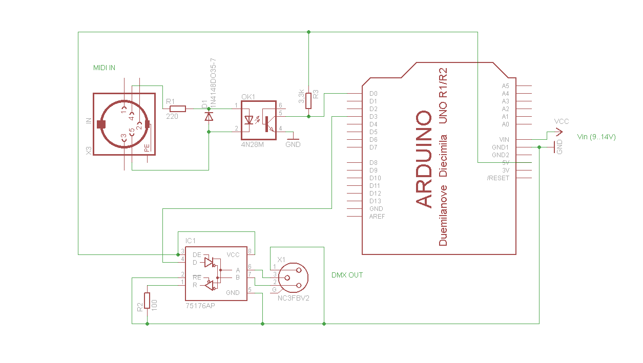
A simple Arduino MIDI-to-DMX control was created for a robot band named Science Fiction Children. The setup consists of two inexpensive LED Par56 lights from Stairville, a basic DMX dimmer pack, and Ableton Live for sound management. The objective...