
Fluid level meter version 2
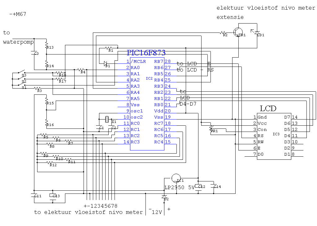
IC4 functions as a critical counter and oscillator combination within the circuit architecture, facilitating the generation of an alternating current (AC) signal essential for subsequent processing. The oscillator's output, available at pin 7, is integral to the operation of the system. The AC signal is modified by a voltage divider network comprising resistors R3 and R4, which attenuates the signal before it is fed into pin 3 of IC5, a multiplexer that selectively routes the signal to various electrodes.
Simultaneously, the AC signal is also directed to a rectifier/demodulator circuit, which consists of diode D1 and resistors R1 and R5. This configuration converts the AC signal into a direct current (DC) voltage that can be analyzed for variations. The rectified signal is then compared against a stable reference voltage using IC2, which operates as a comparator in this scenario.
The operational dynamics of this system become particularly relevant when an electrode is submerged in water. The introduction of water creates an additional capacitive load on the AC signal, leading to a measurable decrease in the output voltage from the demodulator. This reduction is detected by the comparator, which subsequently alters its output level in response to the change. The rapid response of the system is facilitated by the multiplexer, which is designed to connect the AC signal to one electrode at a time, ensuring that the circuit can effectively monitor multiple electrodes in quick succession. This design allows for efficient and accurate detection of changes in the environment around the electrodes, particularly in applications involving liquid detection.IC4 is a counter/oscillator combination and is the key element in the circuit. The oscillator outputs its AC signal on pin 7. This signal is lead (through voltage divider R3/R4) to pin 3 of IC5 (multiplexer IC) which is used as an input. The same signal is also lead to the rectifier/demodulator build up with D1/R1/R5. The resulting rectified signal is compared (with IC2, an opamp) with a constant voltage. If a selected electrode is under water, there will be an extra load on the AC signal, which causes the output of the demodulator to drop a little bit.
The comparator will react by changing its output level. All this takes a fraction of a second because the multiplexer will only handle one electrode at a time by connecting the AC signal to the selected electrode. 🔗 External reference
Related Circuits

A simple audio watt meter circuit or an audio power or audio level meter circuit with diagram and schematics to measure amplifier audio output power in watts. The audio watt meter circuit is designed to measure the output power of...
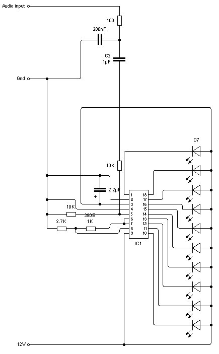
A schematic for an LM3915 VU meter has been created, incorporating a band-pass filter to selectively input portions of the audio frequency spectrum into the VU meter circuit. The intention is to construct five of these circuits to form...
Many beginners trying out their skill with QRP TX for the first time have to overcome many problems before they are able to come on the air. One usual complaint is that everything is working fine, but the signal...

This is a water sensor circuit design based on a Conductive Liquid Level Sensor. This single-chip circuit is compact and simple. It is an AC-excited fluid level sensor, which uses alternating current to provide biasing for the sensor probe,...
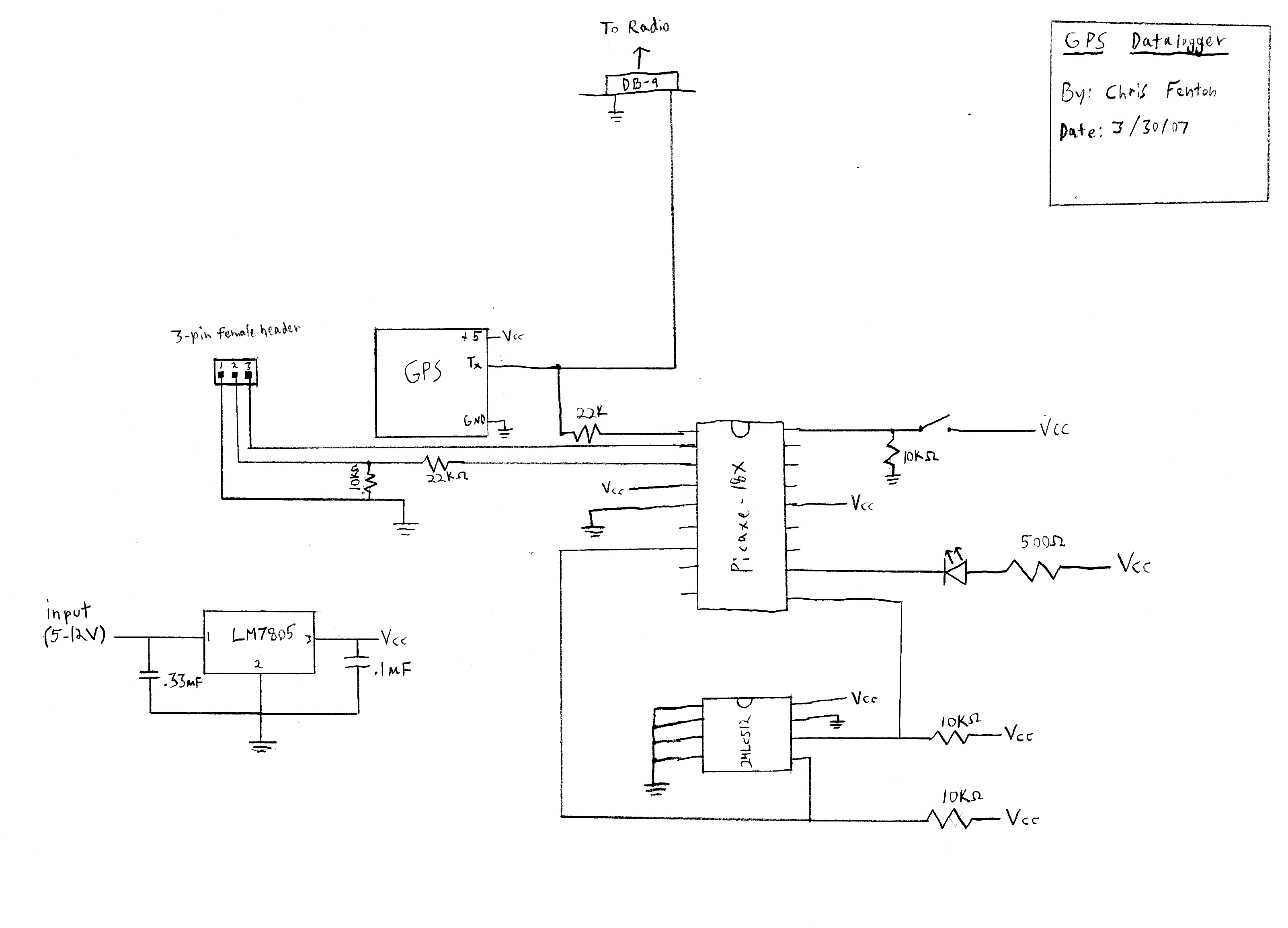
This device was developed rapidly for the USC Rocket Propulsion Lab, which is a student-run high-altitude rocketry initiative at USC. It was assembled shortly before the launch and programmed during travel to the launch site. The device utilizes a...
The project involves displaying the current room temperature using an LM35 temperature sensor. This schematic differs from a previous schematic that utilized a multiplexed seven-segment display. In the earlier schematic, the display select I/O pins were RA0, RA1, RA2,...
Warning: include(partials/cookie-banner.php): Failed to open stream: Permission denied in /var/www/html/nextgr/view-circuit.php on line 713
Warning: include(): Failed opening 'partials/cookie-banner.php' for inclusion (include_path='.:/usr/share/php') in /var/www/html/nextgr/view-circuit.php on line 713