
fluorescent lamp project
Parts and materials:
- B1: Battery, 12 Volt
- C1: Capacitor, 0.1 µF, 25V, Film or Disc
- C2: Capacitor, 0.01 µF, 25V, Film or Disc
- C3: Capacitor, 0.1 µF, 25V, Disc
- D1: Diode, 1N914
- Q1: Transistor, 2N2102, NPN, HS Switch
- R1: Resistor, 12K, 5%, 1/4W, CC
- R2: Resistor, 10K, 5%, 1/4W, CC
- TR1: Transformer, Output or Power, 120Vac/12Vac
The schematic for this circuit will illustrate the arrangement of these components, showing how the battery connects to the driver circuit, which then drives the fluorescent lamp. The blocking oscillator configuration will be highlighted, demonstrating the relationship between the transistor, capacitors, and the transformer. The circuit's design ensures efficient operation and adaptability for various battery types, making it suitable for portable applications such as camping lamps.Compact Fluorescent Lamps [CFL] are low in price, plentiful and easy to find. Unfortunately, the current crop of these lamps seldom lasts as long as their warranty. Usually only the electronics fail and the lamp part of the bulb assembly are still very useable to provide the necessary part for this project. So next time one of those new technology bulbs refused to function convert it to a battery powered camping lamp. Using a saw cut the defunct light bulb apart along the sonic weld area, indicated by the red line in Figure 1. The object of the cutting is to separate and remove the fluorescent lamp from the rest of the circuit.
The electronic circuit is usually on a small round printed circuit board that is loaded with surface mount components. It is possible to diagnose the cause of the failure and repair the lamp. To do this another identical bulb and sufficient patience is a requirement but unless it is a learning project, it is more trouble than what it is worth.
After the cut is completed, mount the lamp with a few 4-40 screws, using the plastic ring on the metal side of an empty coffee can or some other suitable box. The newly built driver circuit, battery and maybe the battery charger can be housed inside that container.
The battery for this project can be some rechargeable type. NiCd (Nickel Cadmium), NiMHd (Nickel Metal Hydride), Li-Ion (Lithium Ion) or sealed lead acid batteries will work properly, only their charger circuit differs. The driver circuit used here is a single transistor, blocking oscillator - Figure 2. Blocking oscillators are nearly ideal to drive fluorescent load because the phosphor glows a relatively long time after each excitation pulse.
The higher the frequency - within reason - the brighter the bulb and the higher the circuit efficiency will be. Operating frequency is set mostly by R2, C2 - Figure 3. Changing the value of the R2 resistor or the C2 capacitor adjusts the frequency and the brightness. Audio or ferrite core transformers are able to work on higher frequencies efficiently than power transformers.
The maximum bulb current should be observed to keep lamp life long. On smaller lamp tubes 10-12 Watts is a reasonable maximum dissipation value. Usual tube ionization voltages are in the 60-80 Volt range. Adjust the value of C3 capacitor if necessary to the lamp on hand to limit the tube current. With pulse drive, higher instantaneous current is permitted. The available voltage depends highly on the transformer turns ratio. For simplicity, an output transformer from a tube or transistor radio can be used, but a custom-made coil wound using an old transformer`s lamination or a ferrite toroid core transformer would work just fine. The transformer for this blocking oscillator had a turn ratio of 20:1 but a 120 Vac/12 Vac small power transformer can also be used.
The complete eight-piece parts kit without the battery and the lamp is available for this circuit for $25 that includes shipping and a suitable transformer. A seven-piece parts kit without the battery, lamp and transformer that includes shipping is $15. Parts are new or recycled. All guaranteed to work. Order here. Parts and materials: B1 - Battery, 12 Volt C1 - Capacitor, 0. 1 uF, 25V, Film or Disc C2 - Capacitor, 0. 01 uF, 25V, Film or Disc C3 - Capacitor, 0. 1 uF, 25V, Disc D1 - Diode, 1N914 Q1 - Transistor, 2N2102, NPN, HS Switch R1 - Resistor, 12K, 5%, 1/4W, CC R2 - Resistor, 10K, 5%, 1/4W, CC TR1 - Transformer, Output or Power 120Vac/12Vac
🔗 External reference
Related Circuits

This circuit powers a 6-inch, 4-watt fluorescent tube using a 12-volt supply, with a current consumption of 300 mA. The circuit designed for powering a 6-inch, 4-watt fluorescent tube from a 12-volt supply consists of several key components to ensure...
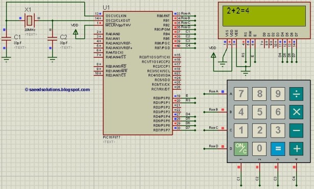
This PIC microcontroller tutorial provides a simple calculator implementation for the PIC16F877 microcontroller. This is a straightforward one-digit calculator. The PIC16F877 microcontroller is a versatile and widely used device in embedded systems, particularly for educational purposes and simple applications. The...
A project called LED Flasher that sequentially flashes LEDs one by one. There is a query regarding the project, and any simple explanation would be greatly appreciated. A reference image or a link can be used for additional context. The...
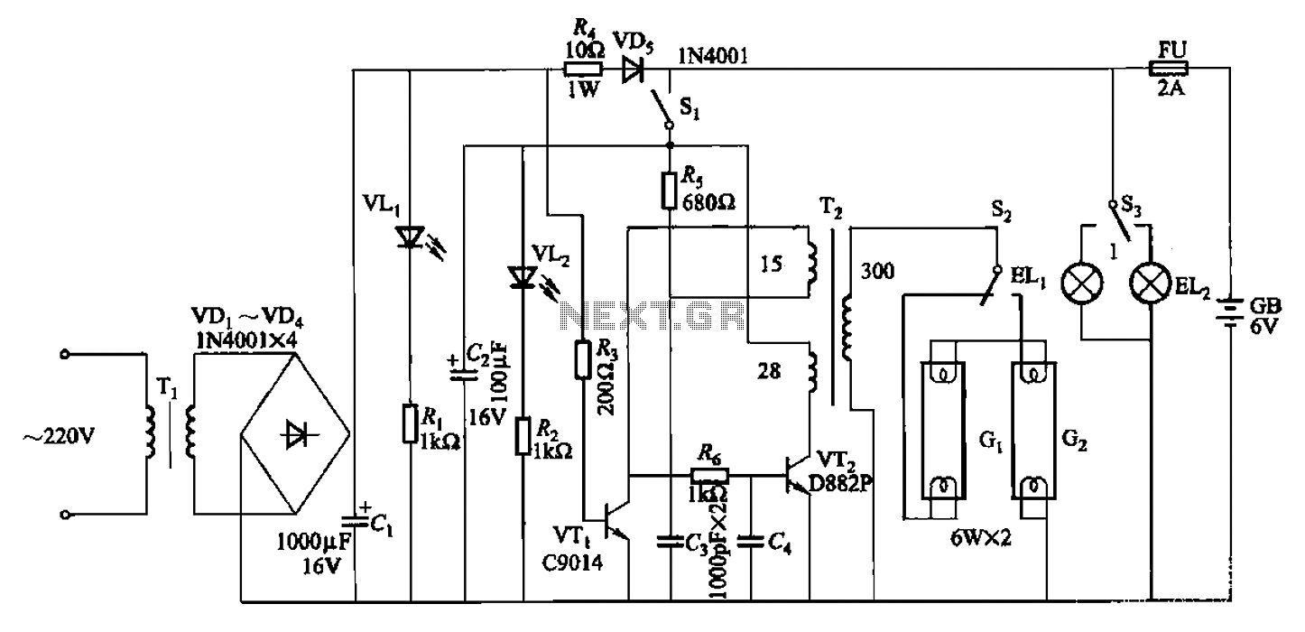
The 786A multi-functional double-tube fluorescent emergency circuit is illustrated in Figure 2-129. This circuit shares similarities with Figure 2-125. The 786A multi-functional double-tube fluorescent emergency circuit is designed to provide illumination during power outages or emergencies. It utilizes two fluorescent...
Since this is a DC circuit, how and where do the positive and negative wires physically connect to the circuit? Where exactly should all the grounds be connected? The schematic indicates the connections to the power source clearly. However,...
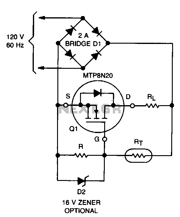
The lifespan of a lamp can be prolonged by enhancing the conditions under which its filament operates. This involves eliminating the inrush overcurrent surge and reducing the mechanical stress (vibration) on the filament caused by an AC source. The...