
flyback inverter for fluorescent lamp 15
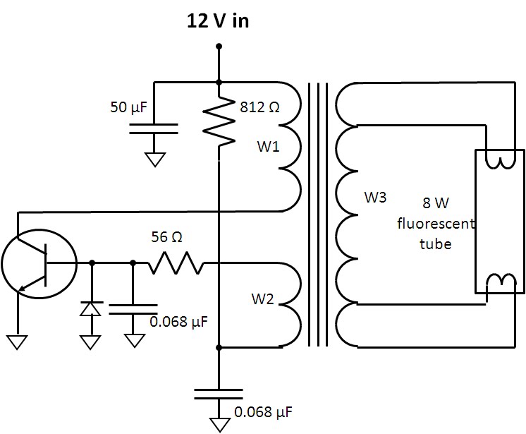
The flyback converter circuit for a fluorescent lamp operates by utilizing a feedback mechanism and energy transfer principles inherent in transformer operation. The circuit typically consists of a switching transistor, a transformer with multiple windings (W1, W2, and W3), and supporting passive components such as resistors and capacitors. The 812-ohm resistor biasing the transistor is crucial for initiating the oscillation process, allowing the transformer to build magnetic flux in winding W1.
As the transistor saturates, the energy stored in the magnetic field is released through winding W3 to the fluorescent tube, producing a high voltage necessary for gas ionization. The transformer’s gapped core design is essential for energy storage, while the saturation mechanism ensures that the inverter oscillates effectively, creating the necessary conditions for continuous operation.
The oscillation frequency of 20 kHz is significant, as it determines the rate at which energy is transferred to the fluorescent tube. The time it takes for the tube to strike, approximately 500 microseconds, indicates the transient response of the system as it ramps up to operational voltage. The transformation of voltage through the turns ratio is critical for achieving the high voltages required for gas ionization, and the design must account for the characteristics of the transformer windings to optimize performance.
In summary, the flyback converter circuit for fluorescent lamps is a sophisticated design that leverages feedback and transformer principles to achieve efficient operation with minimal parts. The careful selection of materials and design parameters can significantly influence the efficiency and effectiveness of the inverter, showcasing the intricate balance between theoretical principles and practical implementation in electronic circuit design.A fluorescent lamp has quite a few unique requirements to get it to start up and stay illuminated. How does this flyback converter manage to do these things I had first looked around to see if I could find a schematic for this fluorescent lamp assembly, but nothing turned up for me. However, the parts count was low enough, and circuit board large enough, that it was a fairly simple matter to trace
out and sketch the inverter`s schematic in fairly short order, as shown in Figure 1. When first powered up the switching transistor is biased on by the 812 ohm resistor, energizing transformer winding W1. This in turn applies positive feedback to the transistor through winding W2, driving it into saturation.
There are two mechanisms in the flyback transformer that are critical for making this inverter work: First it has a gapped core. This allows it to store a substantial amount of energy in its magnetic field which in turn gets dumped over to the fluorescent tube through the secondary winding W3 when the transistor turns off and the transformer`s magnetic field collapses.
During this period the winding voltage continues to climb as the magnetic field collapses until the energy can find a place to discharge to, in this case into the fluorescent tube. The voltage is also further increased by the turns ratio of the transformer. This is the flyback effect that creates sufficiently high enough voltage to get the fluorescent tube to strike or ionize its gas to get it to start conducting and give off illumination, typically many hundreds of volts.
As can be seen this inverter is a very simple circuit with a minimum of parts. A second mechanism in the transformer is it is designed to saturate in order to make the inverter oscillate. At the end of the transistor`s on period the transformer reaches its maximum magnetic flux at which point the transformer saturates.
Winding voltage W2 drops to zero and then reverses driving the switching transistor into cutoff. After the magnetic field has collapsed and energy discharged to the fluorescent tube the process repeats itself. A number of interesting things can be observed in Figure 2. The oscillation period is roughly 50 microseconds, or oscillation frequency of 20 kHz. It takes about 10 cycles, 500 microseconds, for the fluorescent tube to strike. During this initial phase the peak collector voltage is flying up to nearly 100 volts or about 8 times the DC input voltage being applied.
Again, this voltage is being multiplied up by the turns ratio of windings W1 and W2 to bring this up in the vicinity of 600 volts or so needed to make the fluorescent tube to strike. Once the tube does strike and starts conducting its impedance drops. This causes the collector voltage to drop down to about 35 volts which is consistent with the proportion of drop in voltage needed for the fluorescent tube once it`s gas is ionized and is conducting.
Note also the collector voltage pulse also widens as it takes a longer time for the energy in the transformer to be dumped when it`s at a lower voltage. Although this inverter at first glance is a rather simple and minimum viable, minimum parts count circuit, with careful design it can be made to be very efficient.
This is where the design of the transformer becomes as much art as science, knowing how the subtle characteristics of the magnetic material and inductive and capacitive parasitics can be used to advantage in contributing to and improving the overall performance of the design. 🔗 External reference
Related Circuits
The UBA2021 can be utilized as a 600 V lamp controller and half-bridge driver integrated circuit (IC) for high-power applications. It is designed for long-life compact fluorescent lamp (CFL) and tubular fluorescent lamp (TL) applications. The UBA2021 is a versatile...
Fully illustrated and schematized plans for a high-performance, easy-to-build transistorized high voltage flyback driver. The high voltage flyback driver circuit is designed to efficiently convert low voltage DC into high voltage pulses suitable for driving flyback transformers. The circuit typically...
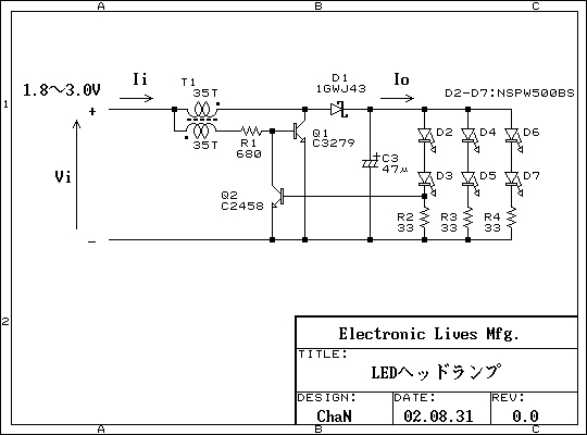
This is a practical white LED head mount lamp (flashlight). Recently many white LED flashlights appear on the market. However, most flashlights require three cells because they are regulating output current with only series resistor. The odd number of...
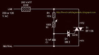
The circuit operates by adjusting the firing angle of the Triac. Resistors R1, R2, and capacitor C2 are involved in this process. The firing angle can be modified by changing the value of any of these components, with R1...
Any step-down DC-DC converter can be utilized as an inverter without modifications to the operating schematic. The only differences between the standard step-down application and the inverting operation are the labels of the connection points. The step-down VOUT is... A...
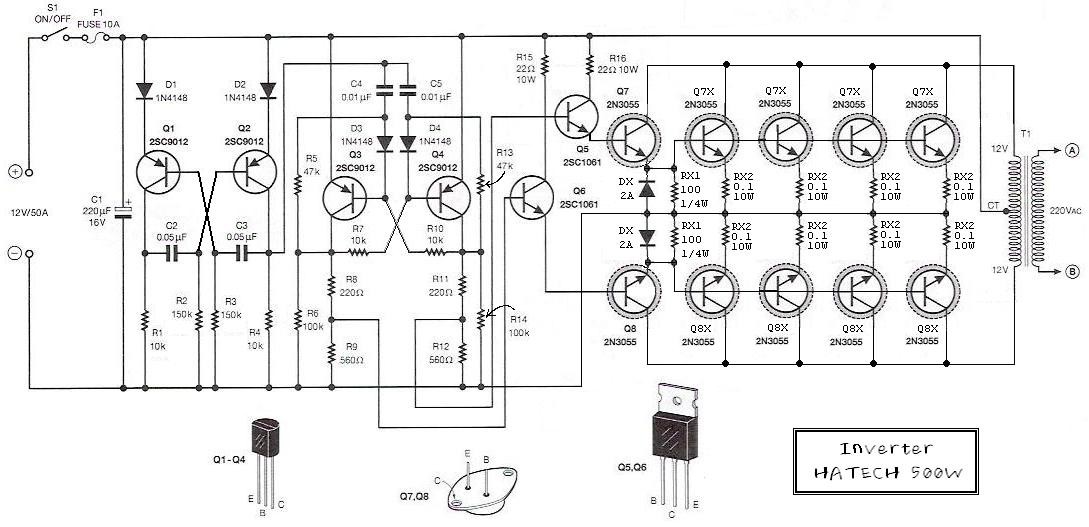
This is the schematic diagram of a 500W power inverter circuit built using 10 pieces of well-known NPN power transistors, 2N3055, to amplify the AC signal produced by a multivibrator. The frequency generator/multivibrator is also constructed using transistors. All...