
Flyback transformer tester circuit using 2SC828

The circuit designed for testing a flyback transformer is essential for diagnosing issues in television sets. Flyback transformers are crucial components in CRT televisions, responsible for generating high-voltage signals necessary for the operation of the cathode ray tube. The proposed circuit is characterized by its simplicity and cost-effectiveness, making it accessible for both hobbyists and professionals in the field of electronics repair.
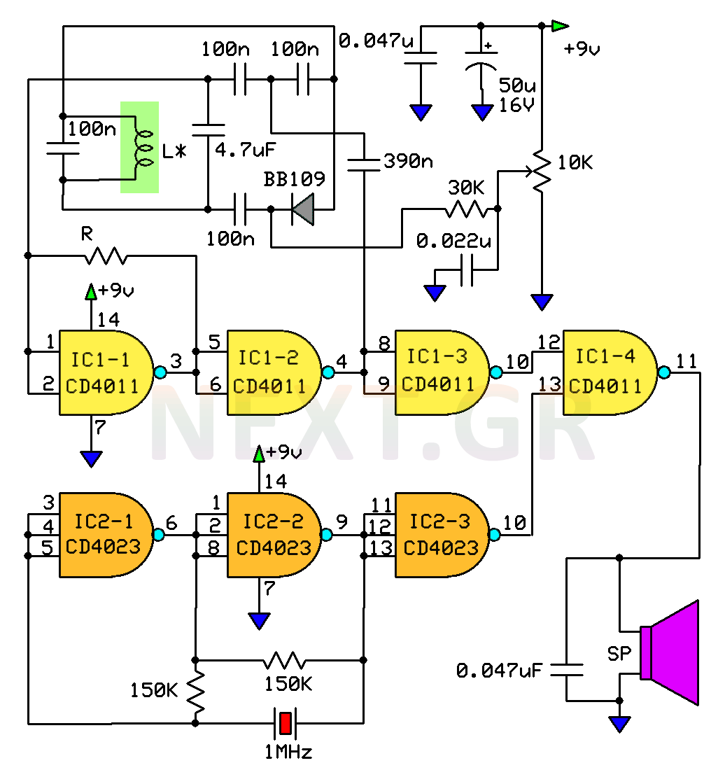
The schematic typically includes a few key components: a power source, a resistor, a diode, and a capacitor, along with the flyback transformer itself. The power source provides the necessary voltage to energize the flyback transformer. The resistor is used to limit the current flowing through the circuit, protecting sensitive components from damage. The diode serves to rectify the output voltage, ensuring that it is suitable for measurement or further processing. Finally, the capacitor may be included to smooth out any voltage spikes and provide stable readings.
When constructing this circuit, attention must be paid to the connections and component ratings to ensure safe operation. Proper insulation and protective measures should be implemented to handle the high voltages generated by the flyback transformer during testing. Additionally, incorporating a method for measuring the output voltage, such as a multimeter, allows for effective diagnostics of the flyback transformer’s performance.
In summary, this flyback transformer testing circuit offers a straightforward and economical solution for television repair technicians, facilitating the identification of faults within CRT televisions. The ease of assembly and the availability of components contribute to its practicality in real-world applications.The circuit tests a flyback transformer of the televisions that the result is a simple, easy and cheap to build. One of my friends is TV repairman colors -.. 🔗 External reference
Related Circuits
I have been researching a "mystery circuit" and I cannot determine its name. Assistance is requested. The inquiry pertains to an unidentified electronic circuit, often referred to as a "mystery circuit." Such circuits can encompass a wide range of configurations...
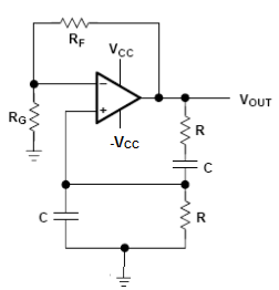
This circuit diagram illustrates a light-activated switch utilizing the National Semiconductor comparator IC LM311 and a light-dependent resistor (LDR). The configuration is based on a voltage comparator circuit centered around IC1. The non-inverting input of IC1 receives a reference...
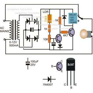
When there is no smoke, the light from the bulb directly illuminates the Light Dependent Resistor (LDR). In this condition, the resistance of the LDR is low, resulting in a voltage drop of less than 6V across it. Consequently,...
The following circuit illustrates the use of the AD8531 integrated circuit for the automatic control of LCD panel backlighting. Features include the ability to compensate for aging effects. The AD8531 is a precision operational amplifier that is well-suited for applications...
This electronic clock comprises the LM8365 and the LDD640R displays. The LM8365 can show the hour/minute and month/day. Users can set two alarm outputs, AD1 and AD2, by pressing either the 12h or 24h button. The operating voltage range...
This circuit is a metal detector designed to detect large metallic objects at depths ranging from 2 to 3 meters, depending on the size of the object and the type of soil. The construction is straightforward, making it accessible...
Warning: include(partials/cookie-banner.php): Failed to open stream: Permission denied in /var/www/html/nextgr/view-circuit.php on line 713
Warning: include(): Failed opening 'partials/cookie-banner.php' for inclusion (include_path='.:/usr/share/php') in /var/www/html/nextgr/view-circuit.php on line 713