
FM Bug detector 80 - 150 MHz
The Mini FM Bug Detector operates as a broad-band receiver, effectively capturing a wide frequency range from 80 MHz to 150 MHz. This capability allows it to detect various transmissions, including those from devices equipped with sensitive microphones. The detection mechanism relies on the feedback whistle produced when a nearby bug is transmitting.
The circuit is designed with a quiescent current of less than 2 mA, making it energy-efficient. The output is delivered through a mini piezo diaphragm, which serves as the audio output. It is important to note that the circuit is not intended to drive a traditional speaker due to its design limitations.
The receiver's architecture is composed of multiple amplification stages, each contributing to the overall gain of the system. The front-end of the circuit is un-tuned, as evidenced by the absence of a capacitor across the inductor. This design choice allows the 20-turn inductor to function effectively at high frequencies without creating a short circuit to ground. Instead, it enables the oscillation of signals around 100 MHz, which are then extracted via a 470 pF capacitor. Lower frequency signals are directed to ground, ensuring that only the desired high-frequency signals are processed.
The initial amplification stages boost the 100 MHz signal, while the audio component is detected at the base of the third transistor through a diode arrangement. The fourth transistor acts as an audio amplifier, specifically designed to drive the piezo diaphragm. An inductor connected across the piezo diaphragm serves a dual purpose: it provides a load for the transistor and generates a high voltage during specific cycles, thereby enhancing the volume output.
To maintain signal integrity, a 22 nF capacitor is employed to filter out high-frequency components from the output signal. Additionally, a 47 µF capacitor is placed across the power supply, which bolsters the circuit's performance by preventing unwanted signals from the output stage from interfering with the front-end circuitry. This arrangement ensures that the Mini FM Bug Detector remains sensitive to incoming signals while minimizing noise and distortion.This Mini FM Bug Detector is basically a broad-band receiver. It picks up the complete band from below 80Mhz to 150MHz and almost anything that transmits in that band will be detected. If a bug with a sensitive microphone is transmitting nearby, the result will be a feedback whistle. The Bug Detector will not determine the output power of a bug as it is detecting the sensitivity of the microphone.
However it will prove the carrier section is working (this is the section that produces the 88MHz frequency) and also the audio section. The circuit is basically a broad-band receiver and will pick up all types of transmissions. The quiescent current for the circuit is less than 2mA and the output is a mini piezo diaphragm. Note: the circuit will not drive a speaker. Each stage provides high gain and the signal is picked up by an un-tuned front-end. You can see the front end is untuned as the inductor does not have a capacitor across it. You would think the 20 turn inductor would create a short-circuit to ground. But signals at 100MHz will oscillate in the inductor and can be picked off via the 470p capacitor. Signals of a low frequency will be taken to ground. The 100MHz signal is amplified by the first two stages and the audio component is detected by the diodes on the base of the third transistor. The fourth transistor is an audio amplifier to drive the piezo diaphragm. The inductor across the piezo provides a load for the transistor and creates a high voltage during part of each cycle to increase the volume.
The 22n capacitor removes the high frequency component of the signal. The 47u across the power supply improves performance of the circuit by preventing signals from the output stage passing to the front end. 🔗 External reference
Related Circuits
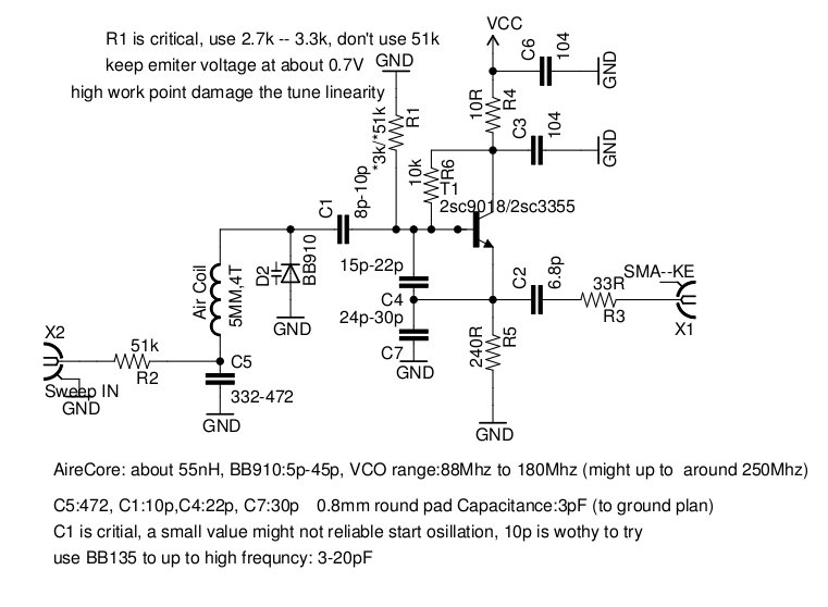
The voltage-controlled oscillator (VCO) is widely utilized in various RF projects, with a particular emphasis on wideband GHz VCOs over VHF/UHF VCOs. This document outlines a Manhattan Island Pad construction for a VHF VCO, operating from low frequencies of...

This schematic diagram illustrates a water level sensor, detector, and monitor circuit. An alarm is also integrated into this circuit. It is designed to detect any fluid with a resistance below 900K ohms. The water level sensor circuit typically employs conductive...
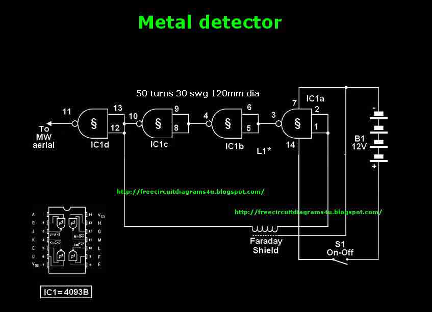
This circuit needs a Faraday shield, which is connected to 0V. To make this one wrap a tin foil around the coil and connect to 0V. Then you can use this circuit to find metal. Tune your mw radio...
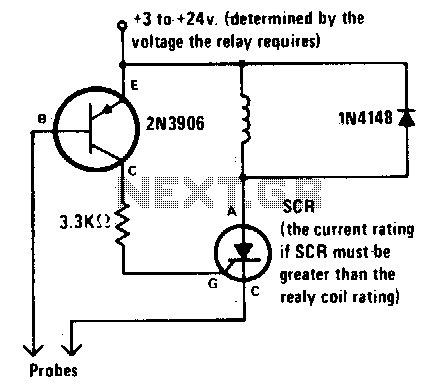
The alarm is activated when the liquid level rises above the probes and remains active even if the level subsequently drops below the probes. This latching mechanism provides an indication that the pre-set level has been reached or exceeded...
Small telephone bug. It listens to the telephone line on an FM receiver. It is self-powered and has a small part count. Circuit diagram, schematics, electronics project. The small telephone bug is a compact and efficient device designed to intercept...

A simple network design is a key feature of the Pierce circuit, as illustrated by these 1-MHz oscillators. Operating the crystal slightly above resonance requires only one high-gain transistor stage. Operating it exactly at series resonance requires an additional...