
FM carrier current remote speaker system
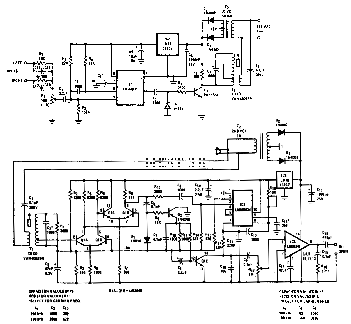
The wireless FM transmitter and receiver system designed for power line communication utilizes existing electrical infrastructure to transmit audio signals effectively. The transmitter converts audio signals into FM radio waves, which are then coupled onto the power lines, allowing for transmission over substantial distances without the need for additional wiring. The system's design ensures minimal interference and noise, which is crucial for maintaining audio fidelity, particularly in environments with multiple electrical devices.
The frequency response specification of 20 Hz to 20 kHz indicates that the system is capable of transmitting the full range of human hearing, making it suitable for high-fidelity audio applications. The low total harmonic distortion (THD) value further emphasizes the system's capability to deliver clear and undistorted sound, which is essential for both speech and music transmission.
The inclusion of dual input terminals allows for flexibility in audio source selection. Users can connect a stereo audio source, and the system will mix the left and right channels into a mono signal for transmission to a single speaker. This feature is particularly advantageous in scenarios where only one speaker is available or desired.
The receiver component is responsible for demodulating the FM signal received over the power lines. It amplifies the signal to ensure adequate sound levels and applies limiting to prevent distortion during high-volume passages. The audio mute function enhances user experience by silencing the output when no carrier signal is detected, preventing unwanted noise during silent periods.
The output capability of 2 W to a speaker is suitable for typical residential applications, providing sufficient power to drive standard speakers effectively. This system is ideal for home entertainment setups, allowing users to enjoy high-quality audio throughout their living space without the need for complex wiring. The overall design and functionality of this wireless FM transmitter and receiver system make it a versatile solution for audio transmission over power lines.High quality, noise free, wireless FM transmitter/receiver operates over standard power lines. Complete system is suitable for high-quality transmission of speech or music, and will operate from any ac outlet anywhere on a one-acre home site. Frequency response is 20-20, 000 Hz and THD is under Transmission distance along a power line is at least adequate to include all outlets in and around a suburban home and yard
Two input terminals are provided so that both left and right signals of a stereo set may be combined for mono transmission to a single remote speaker if desired. The receiver amplifies, limits, and demodulates the received FM signal. It provides audio mute in the absence of carrier and 2 W output to a speaker. 🔗 External reference
Related Circuits
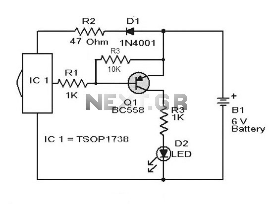
A simple remote control tester circuit with a diagram and schematic using the infrared sensor IC TSOP1738. An LED will blink when infrared waves fall on it, indicating the remote control is functioning. The remote control tester circuit utilizes the...
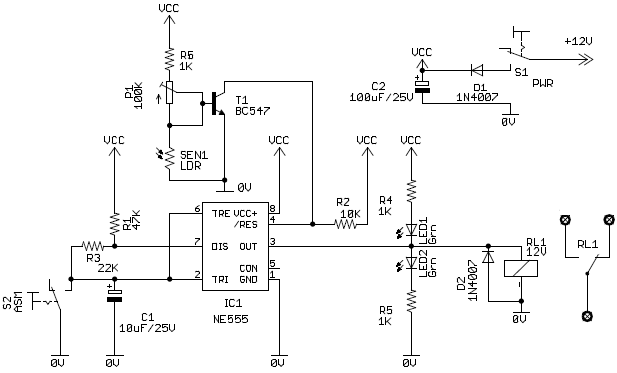
When a vehicle is driven on the highway at night, it is essential that the light beam is of high intensity and illuminates the road at a sufficient distance. To achieve optimal visibility during nighttime driving, especially on highways, the...
The power-supply sequencing tutorial utilizes the MAX16046 system-management integrated circuit (IC). The configuration software facilitates the setup of tolerances and the sequence order. The MAX16046 is a versatile system-management IC designed to manage power-supply sequencing in complex electronic systems. It...
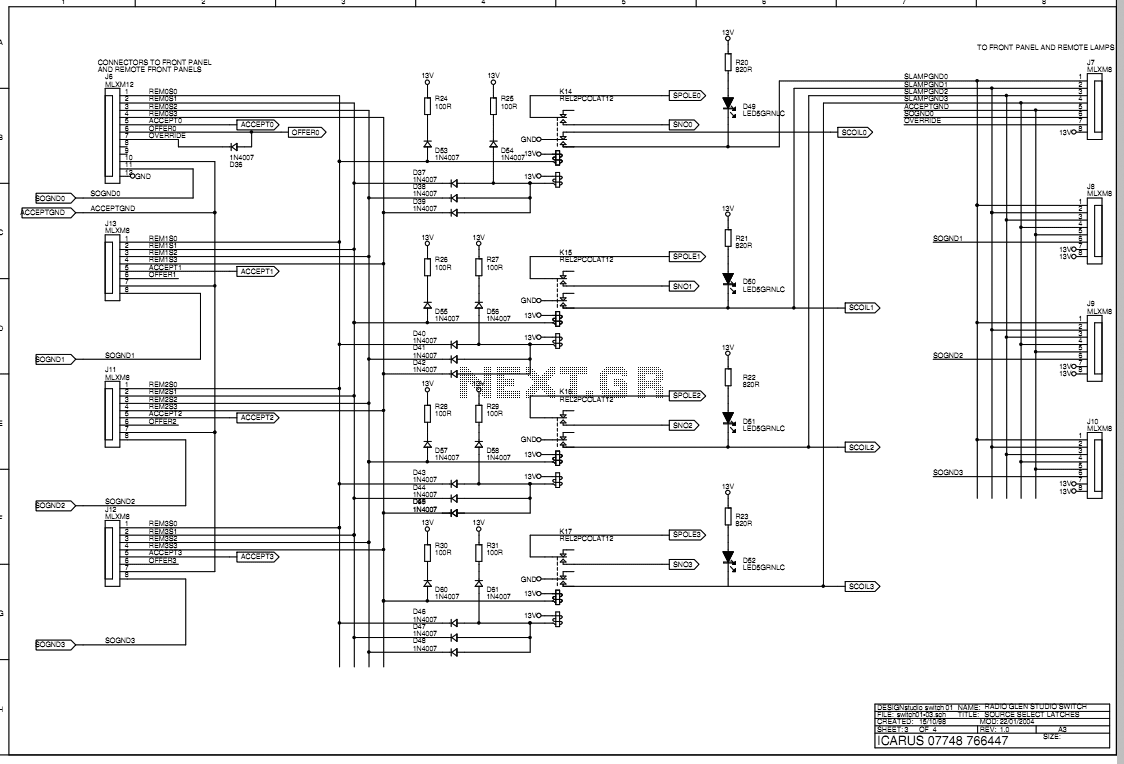
The main box of the Transmit Selector system is designed to be located in the technical rack of a small radio broadcast station. There are four stereo balanced line inputs, either of which can be routed to a stereo...
This is a discrete high-current switch-mode LED driver circuit. The fundamental principle of this circuit is based on the buck-converter topology. The efficiency of this circuit is 80%. The discrete high-current switch-mode LED driver circuit utilizes a buck converter configuration...
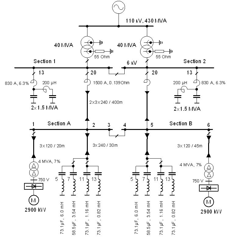
The vertical line indicates the instance of the 5th harmonic filter connection. The diagram illustrates the power system with the designed group of single-tuned filters for a system with a DC drive supplied by a 6-pulse controlled rectifier: PN...
Warning: include(partials/cookie-banner.php): Failed to open stream: Permission denied in /var/www/html/nextgr/view-circuit.php on line 713
Warning: include(): Failed opening 'partials/cookie-banner.php' for inclusion (include_path='.:/usr/share/php') in /var/www/html/nextgr/view-circuit.php on line 713