
FM HF OSCILLATOR WITH NO VARACTOR
The described circuit presents an innovative solution for frequency modulation in high-frequency oscillators by leveraging base-charging capacitance modulation. This method is particularly advantageous in applications where maintaining low power consumption is critical, such as in portable and battery-operated devices. By avoiding the use of a varactor, the circuit mitigates the issues associated with the substantial voltage swings that typically accompany varactor-based modulation systems.
The ceramic coaxial quarter-wave resonator, designated as T1, plays a pivotal role in this configuration. The resonator is designed to resonate at a specific frequency, which is determined by its physical dimensions and the dielectric properties of the ceramic material. This resonant behavior allows for efficient energy transfer and stability in frequency modulation, enhancing the overall performance of the oscillator.
In this circuit, the modulation of frequency is achieved through the manipulation of the capacitance at the base of the oscillator. As the base-charging capacitance varies, it directly influences the oscillation frequency, allowing for precise control without the drawbacks of high voltage requirements. This approach not only simplifies the design but also improves the reliability and efficiency of the oscillator in various applications, including telecommunications and signal processing.
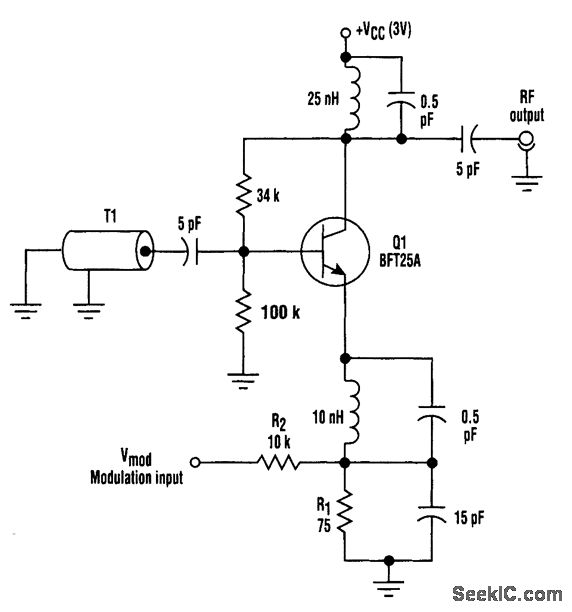
Overall, this circuit design exemplifies a practical and effective method for achieving frequency modulation in high-frequency oscillators, providing an alternative that is particularly suitable for low-voltage environments.Instead of using a varactor to frequency-modulate a high-frequency oscillator, this circuit uses base-charging capacitance modulation. Consequently, the large voltage change required by a varactor, which can be a major problem in battery-powered systems with limited supply voltages, is elimtnated.
T1 is a ceramic coaxial quarter-wave resonator. 🔗 External reference
Related Circuits
A Crystal Colpitts oscillator can be constructed using a parallel mode crystal and a transistor. The circuit is depicted in the accompanying figure. In this configuration, an inductance is utilized. The Crystal Colpitts oscillator is a type of electronic oscillator...
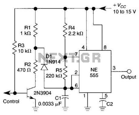
A 1-kHz gated oscillator with no long turn-on cycle is shown. R2, R3, and D1 preset the voltage on tuning capacitor C1 to a percentage of the supply voltage. The circuit described functions as a gated oscillator operating at a...
In this version of the oscillator, Rb is a small incandescent lamp. Typically, R1 = R2 = R and C1 = C2 = C. During normal operation, Rb self-heats to the point where its resistance is Rf/2. A Wien...
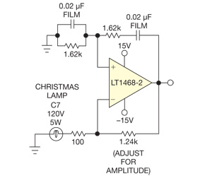
A low-distortion Meacham-bulb-stabilized Wien-bridge oscillator is utilized to acquire the FFT of a pure sinusoid at approximately 5 kHz. The Meacham-bulb-stabilized Wien-bridge oscillator is a precision oscillator circuit that generates a sine wave output with low distortion. This type of...
Below are a couple circuits you can use to produce a 32.768 KHz square wave from a common watch crystal. The output can be fed to a 15 stage binary counter to obtain a 1 second square wave. The...

This oscillator may contain several switched crystals to provide channelized operation. A buffer amplifier may be added if desired. The oscillator described is designed to utilize multiple switched crystals, enabling it to operate across various frequency channels. This feature is...