
FM radio circuit
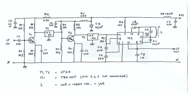
The described circuit consists of two amplifier stages utilizing SF215 transistors, which can be substituted with BF240, BF241, BF254, BF255, BF594, or BF595 transistors, offering flexibility in component sourcing. These amplifier stages are interconnected by ceramic filters designed for a 10.7 MHz intermediate frequency (IF), which is a standard frequency used in FM demodulation. Following the amplifier stages, an FM demodulator is implemented using the TBA120T integrated circuit, which is specifically designed for FM signal processing.
The output from the demodulator is routed through a 100k logarithmic potentiometer, allowing for volume control before it reaches the audio output stage. The design emphasizes the use of readily available components, as demonstrated by the choice of transistors and the use of salvaged parts, which enhances both sustainability and cost-effectiveness.
In the power supply section, a 2 x 12V, 1.5A wall adapter supplies power to the circuit. The output is smoothed by a 6800 µF / 100V capacitor, which is charged through two BY298 diodes, ensuring rectification and filtering of the AC input. The voltage regulation is managed by a Motorola MC78T12CK integrated circuit, which provides a stable 12V DC output. To enhance stability and transient response, a 10µF tantalum electrolytic capacitor is placed in parallel with a 10nF ceramic capacitor at the output of the voltage regulator, effectively improving the power supply's performance.
Audio quality is critically influenced by the choice of loudspeaker. In this instance, a vintage Philips AD3700M/06 speaker has been selected, noted for its dual-cone design and specifications suitable for the application. The speaker features a 14 cm diameter, a power rating of 6 W, an impedance of 5 Ohms, and an efficiency of 6%, making it capable of reproducing a frequency range from 90 Hz to 18 kHz. The speaker's magnetic field strength of 9,500 Gauss indicates a robust design, contributing to its longevity and performance, even after decades of use. This combination of modern and vintage components reflects a thoughtful approach to audio circuit design, balancing performance with resourcefulness.Two conventional amplifier stages built with SF215 transistors are linked by ceramic 10.7MHz IF filters, and followed by an FM demodulator built with a TBA120T i.c. Straight from the databook. Output goes via a 100k log potmeter (not shown) to the audio stage. (NB SF215 transistors can be replaced by BF240, BF241, BF254, BF255, BF594 or BF595). Since my junkbox does not contain TIP41s, I made a Japanese version, using 2SC945, 2SA564A and 2SD1138s salvaged from damaged Oriental stereos.
The amplifier sounds great and is unconditionally stable. The power supply is also made from junkbox parts. A 2 x 12V, 1.5A wall-wart (computer item) feeds a 6800 µF / 100V smoothing capacitor via two BY298 diodes. A Motorola MC78T12CK i.c. (3A regulator in TO-3 package) provides 12V DC. For stability’s sake I placed a 10µF tantalium electrolytic parallelled by a 10nF ceramic capacitor directly between the output terminal of the MC78T12CK and ground.
Audio quality is strongly dependent on the employed loudspeaker. I tried various modern speakers but finally opted for an ancient model salvaged from an empty radio cabinet (Philips AD3700M/06). Valve radio specialist John Hupse (http://www.hupse.eu/radio/speakers/AD3700.htm) lists the following specs for this item: dual-cone, diameter 14 cm, power 6 W, impedance 5 Ohms, efficiency 6%, frequency 90-18,000 Hz, strength of the magnetic field 9,500 Gauss (26,200 Maxwell).
It dates from 1961 and is still going strong after 46 years. 🔗 External reference
Related Circuits
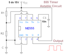
A type of relaxation oscillator comprising two stages that are interconnected such that the input of one stage is derived from the output of the other. This configuration essentially consists of two amplifiers cross-coupled with regenerative feedback in its...
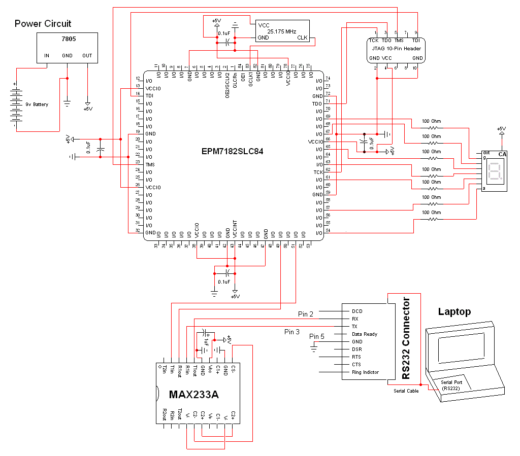
The schematic for this project is a modified version of the CPLD development board schematic. Several new components have been added for this project, and the completed schematic can be viewed below. The main components in the schematic are...
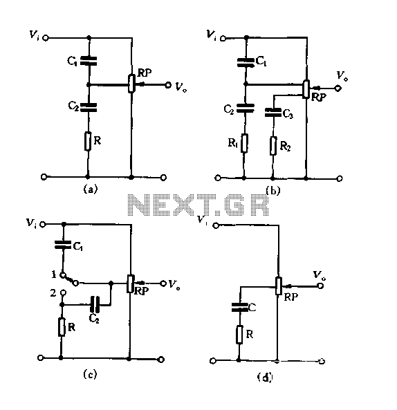
Figure 1.88 illustrates the loudness control circuit utilizing multiple taps on a potentiometer. In Figure (A), the connection is made between the tap and the potentiometer's input, along with the ground. An RC compensation network is employed, where the...
The Electronic Dazer is a modern, portable, personal-protection appliance. It generates high potential energy to ward off vicious animals or other attackers. It is an aid to help escape from a potentially dangerous situation. The device develops about 2,000...

This optodetector measures the position of the ball by the amount of light transmitted by the infrared LED. It generates a linear signal across the small area of the detector, rather than simply providing an "on" or "off" output....
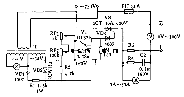
The charging apparatus depicted in the schematic circuit has a maximum output current of 20A and a maximum charging voltage of 80V. It can be adjusted starting from 0V, making it suitable for charging various types of batteries. The...