
FM transmitter circuit diagram overvoltage protection
The FM302E-I-type FM transmitter exciter is a sophisticated device integrated into Japan's NEC HPB a 1210 motherboard, employing advanced techniques such as direct carrier frequency modulation and phase-locked frequency stabilization. The preamplifier stage utilizes a BLF-177 FET, which is capable of delivering up to 150W of output power. This output is directed through a circulator to the subsequent tube amplifier stage, which acts as the final amplification stage in the transmitter's architecture.
The power supply for the preamplifier is managed by the integrated power regulator 4NICK48; however, the absence of an overvoltage protection circuit poses a significant risk. In the event of an overvoltage condition, the BLF-177 tube can fail, resulting in a dangerous scenario where the actuator may still function normally, yet the overall system experiences a loss of power output. This situation was evidenced when the integrated 48V power supply output was measured at 84V, indicating a fault condition that could lead to repeated failures of the amplifier tube.
To mitigate these risks, the design of an overvoltage protection circuit is proposed. This circuit must be robust enough to handle the specific challenges faced by transmission equipment, particularly in regions prone to thunderstorms and lightning strikes. The protection circuit is designed to monitor the voltage levels continuously, ensuring that the power supply is disconnected if the voltage exceeds a predetermined threshold of 52V. This threshold is critical, as it is slightly above the normal operating voltage of 48V for the BLF-177 FET, providing a safety margin to prevent damage.
The schematic of the protection circuit includes various components such as a transformer for stepping down the voltage, a three-terminal voltage regulator for providing a stable 12V DC output, and a relay system that engages or disengages the power supply based on the voltage readings. The relay operates in conjunction with a solid-state relay, allowing for quick response times to overvoltage conditions. The entire assembly is designed to be user-friendly, with a terminal board that simplifies connections and facilitates easy maintenance.
The implementation of this overvoltage protection circuit not only enhances the reliability of the FM transmitter system but also significantly reduces the likelihood of damage due to electrical surges. By incorporating this protective measure, the overall operational integrity of the transmitter is preserved, thus ensuring continuous and high-quality broadcasting capabilities while minimizing potential repair costs associated with amplifier tube failures.FM302E-I-type FM transmitter exciter is used in Japan NECs HPB a 1210 motherboard. Direct carrier frequency modulation, phase-locked frequency stabilization and frequency synth esis. Preamplifier (BLF-177 FET) directly driven by an actuator, the maximum output power of 150W. Via the circulator to the last stage, as the final stage tube amp pushing stage. Pre-amplifier power supply with integrated power 4NICK48. Unfortunately, the present level no overvoltage protection circuit and DC voltage indication, so that the level sometimes happen that failure: actuator output normal, no power output at the same level, no final power output. The investigation is BLF177 amplifier tube breakdown burning ring, disconnect the power supply load, measured integrated 48V power supply output is 84V.
Failure is part of the fault 4NICK48 integrated power regulator, 84V fault voltage amplifier tube BLF177 the breakdown burn again. Because of the power supply is fully sealed and can not be repaired. The integrated power amplifier tube and more expensive, the loss is very large. Therefore, it is necessary to present the power amp tubes plus over-voltage protection circuit, especially my station is located in the mountains above the summer thunderstorm season, often in series with the power line lightning, burned transmission equipment.
Plus overvoltage protection circuit for safe, high quality broadcast off the air to reduce the rate, and save a lot of money. We use the library of existing components, design overvoltage protection circuit is shown, and install a terminal board, wiring simple, simple control, low cost, reliable experiments, very practical value.
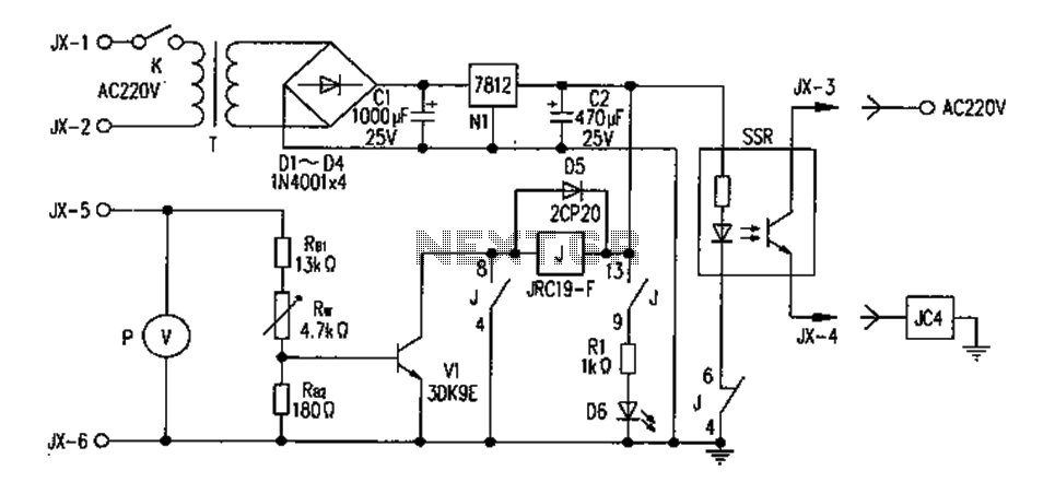
A copy of the protection circuit works described below, schematic diagram shown in Fig. FIG JX-based protection small box terminal board, fixed on the small box above, JX-1, JX-2 220V AC power connection; JX-3, JX-4 series with the transmitter control high voltage AC contactor block JC4 line package loop, this contact with the machine to control the high-pressure gear; JX-5, JX- * 8V voltage sampling. K-based small box work switch (OFF/ON). The switch in the protection circuit, as a reset switch, closing the re-closed. T for the input 220V, output 15V AC transformer. As the power supply of the device. Three-terminal power supply LM7812 + 12V DC output voltage. P 48V voltage for newly added instruction sheet (full scale 100V). V1 for the switching transistor (3DK9E), RB1, RB2, RW for the bias resistor (and sampling set circuit), RB1 13k.
RB2 180 .RW 4.7k. J for small electromagnetic relay. Model: JRC-19F/012M.D5 protection diode (2CP20), D6 light emitting diode (red µ5mm), SSR for the exchange of solid state relays (model: JGX-2F). Protection control principle: RB1, RB2, RW sampling voltage divider circuit composed of 48V, when the power amplifier is normally + 48V, the adjustment potentiometer RW make V1 base voltage of 0.5V cutoff switch transistor V1, V1 collector to a high level.
relay J does not pull its normally closed contact (4,6) is turned on to give a solid state relay SSR 12V input voltage and conduction, high-voltage AC contactor control block (~ 220V) JC4 pull, control high-pressure gear enter the normal working condition. When the 48V power amplifier exceeds 52V (this FET operating voltage of 48V. The maximum operating voltage is less than 52V, thereby protecting from the control voltage should be set to 52V).
V1 switch group extremely 0.65V. This tube saturated conduction, the collector is low, the relay pull-J by J (4.8) normally open contacts self-protection (as 100W power amplifier controlled by a high-pressure gear. Block after block high voltage. The role is to protect themselves prevent 48V 100W power amplifier sampling circuit failure, causing relay alternately pass, off); J, electromagnetic relay normally closed contact (4,6) is disconnected, solid state relay SSR 12V input voltage cutoff lose, JC4 line package power release, blocking high-pressure gear.
100W power amplifier and then blocked, has protective effects. After identification and cause of the fault, the switch K closed off a little longer. The protection circuit is reset, the protection circuit into the next real-time protection status. Pretend after the first simulation protection experiments. Get a l: 1 The 220V isolation transformer and a voltage regulator. Assembled into a rectifier, filter power supply voltage output range between O-100V adjustable sampling voltage and analog 48V as 84V power supply failure, connect the protection circuit to test adjustment:. RW the sampling voltage at 48V, the relay J does not suck, normally closed contact (4,6) is turned on, AC solid state relay output series AC 220V25W incandescent bulb turned on shiny, high-voltage block simulation is working properly; when the sampling voltage is greater than 52V, the sampling voltage adjustment RW when 52V J pull the relay, normally closed contact (4,6) disconnect, AC solid state relay output is turned off, the incandescent light bulb goes off, the protection circuit simulation protection work.
Then again change the regulator output: test J is working, through experiments and measurements can work as designed. The protection device on the machine to work. Up to now has been working for many years, the phenomenon has never been a malfunction of the pre-amplifier repeatedly play a protective role.
The transmitter is connected with the overvoltage protection circuit: over-voltage protection circuit wiring board Jx-1, JX-2 AC 220V input connected, respectively, then the transmitter terminals X1-1, X2. JX-3 with JX-4 in series among JC4 line package line; JX-5, JX-6 were connected to the use of solid state power amplifier integrated power 4NICK48 positive and negative ends (that is, plug the transmitter connected XS4-14, XS4-12 feet), as 48V sample voltage.
Voltmeter and JX-5, JX-6 terminals.
Related Circuits
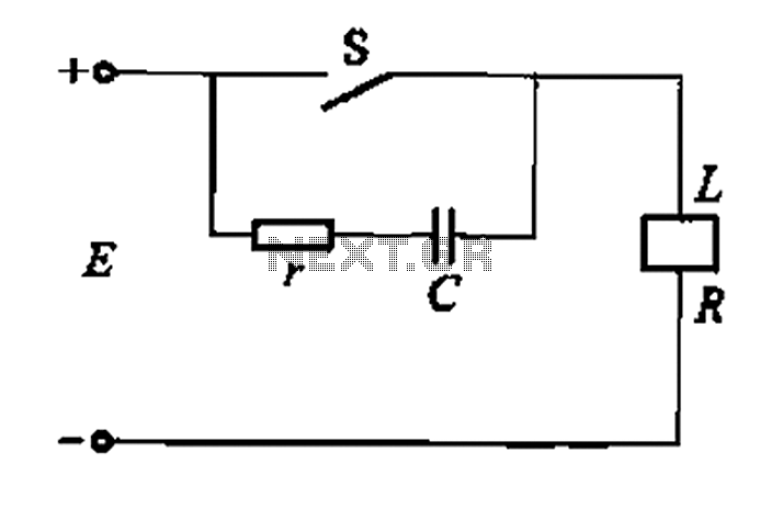
A resistor-capacitor circuit designed to prevent spark blowout. The coil's magnetic energy is converted into electrical energy stored in the capacitance C, effectively suppressing sparks and enhancing safety. The circuit is capable of functioning normally even with reverse polarity....
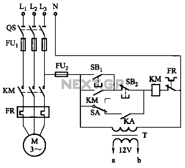
The circuit illustrated in Figure 3-81 employs a transistor delay circuit to facilitate start-stop cycle control. It can operate in both manual and automatic modes. The circuit is primarily governed by the motor run time circuit, which includes transistors...
This circuit can manage nine independent telephones using a single telephone line pair located at nine different locations. It functions as a bidirectional telephone line simulator without the need for actual telephone lines, allowing for coupling, testing, and demonstration...
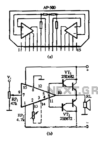
The AP500 is a high-performance dual-channel FET DC amplifier driver module designed for high operating voltage applications. It features push power, low distortion, a wide frequency response, and a simple external circuit. Utilizing superior resistance characteristics in audio circuits,...
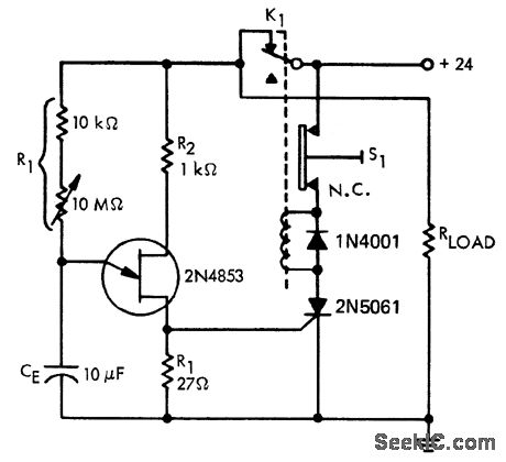
A time delay circuit utilizing a Unijunction Transistor (UJT). The maximum time delay is adjustable via a 10 MΩ potentiometer, allowing the time delay to be configured from less than one second to approximately 2.5 minutes, as referenced by...
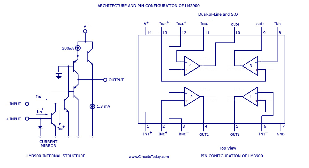
A simple multi-channel audio mixer circuit utilizing the LM3900 quad amplifier is presented below. The circuit features a four-channel quad amplifier (LM3900) with two microphone audio inputs and two direct line inputs. By paralleling additional circuits, the number of...