
fm transmitter colpitt oscillator
A comprehensive analysis of the described FM transmitter circuit reveals several key components and their roles in achieving frequency modulation. The microphone captures audio signals and converts them into a corresponding electrical signal. This signal is initially decoupled by capacitor C1, which removes any DC offset, ensuring that only the AC component of the audio signal is amplified.
Transistor Q1 acts as the primary amplifier in the circuit. It increases the amplitude of the audio signal, allowing it to drive subsequent circuit elements effectively. After amplification, capacitor C2 further decouples the signal, ensuring that any remaining DC components do not affect the following stages of the circuit.
The combination of resistor R6 and capacitor C3 forms a low-pass filter that attenuates high-frequency noise, allowing only the desired frequency components to pass through to the next stage. This filtering is crucial for maintaining the integrity of the audio signal before it is modulated.
In the frequency modulation (FM) stage, transistor Q2 plays a vital role. The frequency modulation is achieved by varying the base voltage of Q2, which directly influences the base-collector capacitance. This variation in capacitance alters the resonant frequency of the tuned circuit, resulting in frequency deviation proportional to the input audio signal. The equation governing this modulation can be represented as cos(2πf_ct + fΔ), where f_c is the carrier frequency, and fΔ represents the frequency deviation caused by the modulating signal.
The design should also consider external influences, such as nearby objects affecting the antenna's performance and the drift in frequency as the power supply voltage decreases. To ensure stable operation, it is recommended to analyze and possibly incorporate a defined, stable frequency FM transmitter design, which includes proper coupling to an antenna and harmonic suppression filters. Searching for well-documented schematics of such FM transmitters can provide valuable insights and guidance for building a reliable circuit while adhering to the goal of maintaining a transistor-level design, avoiding the use of operational amplifiers or integrated circuits.C1 takes the DC decoupled voltage from the Microphone, amplifies this via Q1, C2 decouples it again, then R6 and C3 Low Pass Filter it, but once we get to Q2, Secondly how does this circut actually accomplish frequency modulation: Please use math on me! (I know that it should change the delta F term in the equation cos(2*pi*fc*t + F) to achieve FM, or more
correctly: cos(2*pi*fc*t + f* «(messageSignal) Frequency deviation is accomplished by changes to the base voltage. This affects the Base-Collector capacitance. The tuned circuit is also changed when anything gets near the antenna and of course it drifts as the battery wears down.
My goal is just to build a simple transistor level FM transmitter for my own amusement. More of an exercise on what I`ve learned as an engineer because I want my masters degree to be in Communications Systems and Signal Processing Edit: My bad, we were discussing a different transmitter in that thread, but some of the discussion might still be useful. I have an article on your transmitter, but I can`t find it right now. If I run across it, I`ll post. My goal is just to build a simple transistor level FM transmitter for my own amusement. More of an exercise on what I`ve learned as an engineer because I want my masters degree to be in Communications Systems and Signal Processing Do your self a favour and analyse the circuit of a REAL FM transmitter, one which has a defined, stable frequency, one which has sensible coupling to a defined antenna and harmonic supression filters.
Could you provide me with places that have such clearly explained and defined schematics It becomes rather difficult to find such high level designs. I would really rather work at the transistor level (i. e. , no OPAMPs or ICs, including multipliers) 🔗 External reference
Related Circuits
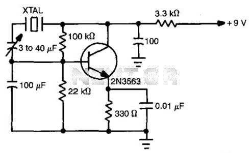
This simple circuit will oscillate with a wide range of crystals. Connect several different types of crystal holders in parallel to improve versatility. The 3 to 40 pF capacitor adjusts crystal frequency over a small range for setting to...
I have had requests to add a VHF FM transmitter, to the QRP collection. This project is a simple transmitter using only one crystal and will cover 145.00 to 146.00 MHz. The crystal is a 44.9333 MHz crystal for...
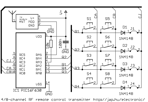
This is a general purpose remote control project with using programmable PIC microcontrollers. Schematics are shown for using infrared (RF) or radio (RF) media. If you are not familiar with microcontroller programming, you can use fixed encoder and decoder...
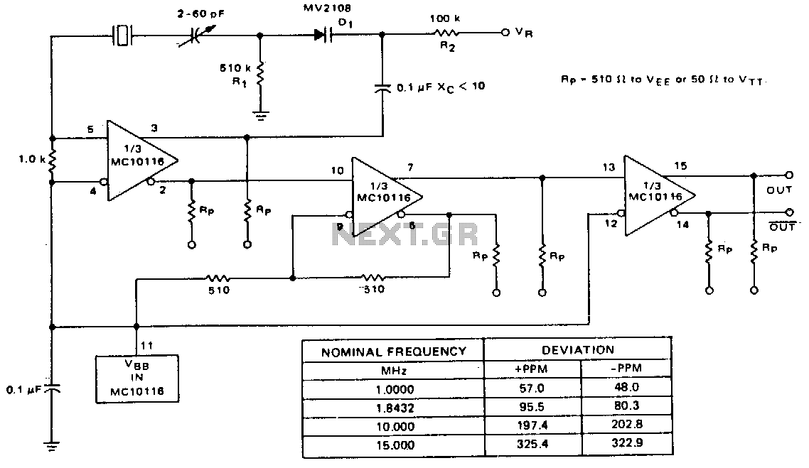
A voltage-variable capacitance tuning diode is connected in series with the crystal feedback path. Adjusting the voltage on the variable resistor (VR) changes the capacitance of the tuning diode, which in turn tunes the oscillator. The 510 kΩ resistor...
The following circuit illustrates an FM transmitter circuit diagram operating within the 88-108 MHz frequency range. Features include a 1W transmitter of the Tetsuo style. Components involved are capacitors, among others. The FM transmitter circuit operates in the VHF band,...
Op-amps have been widely used in low-frequency oscillators. Op-amps, or operational amplifiers, are versatile components frequently utilized in the design of low-frequency oscillators. These devices are capable of generating periodic waveforms, such as sine, square, or triangular waves, which are...