
FM Transmitter with 2N2218
The FM transmitter circuit operates by converting audio signals from the electret microphone into radio frequency signals. The 2N2218 transistor serves as the main amplification element in this circuit. The electret microphone picks up sound waves and converts them into electrical signals, which are then fed into the base of the transistor.
The circuit typically consists of a few key components: the electret microphone, the 2N2218 transistor, resistors, capacitors, and the antenna. The microphone is powered by a biasing resistor connected to a suitable voltage source, often a battery. The output from the microphone is coupled to the base of the transistor through a coupling capacitor, allowing only the AC audio signals to pass while blocking any DC components.
The transistor amplifies the audio signal, which is then modulated onto a carrier frequency. This modulation process allows the audio signal to be transmitted over radio waves. The output from the collector of the transistor is connected to the antenna, which radiates the modulated signal into the surrounding environment.
The length of the antenna plays a crucial role in determining the transmission range and quality of the signal. A copper wire antenna between 15 to 40 cm is typically used, as it is well-suited for the frequency range of the FM band. The choice of length can be adjusted based on the desired frequency of operation, with shorter lengths generally favoring higher frequencies.
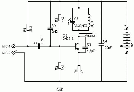
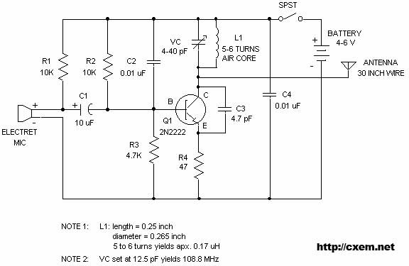
Additional components may include capacitors for frequency stabilization and resistors for setting the biasing levels of the transistor. The overall design of the circuit is straightforward, making it suitable for hobbyists and educational purposes in understanding basic radio frequency transmission principles. Proper layout and component selection are essential to achieve optimal performance and minimize interference in the transmitted signal.Here`s simple FM transmitter circuit using medium power 2N2218 transistor. Micropohone is of electret type that connects to two input terminals and the antenna should be a copper wire from 15 to 40 cm. Below is schematic circuit of the fm transmitter.. 🔗 External reference
Related Circuits
The TPTG transmitter has been transformed into a modern TNT model. This transmitter can utilize the existing K-111 power pack for both the transmitter and receiver, eliminating the need for a separate power supply unit. Building this compact transmitter...
A basic UUS 65-73 MHz FM transmitter circuit schematic that can be utilized as a UUS oscillator. The frequency range is 65 - 73 MHz. The UUS 65-73 MHz FM transmitter circuit is designed to operate within the specified frequency...
This circuit is a simple two transistor (2N2222) FM transmitter. No license is required for this transmitter according to FCC regulations regarding wireless microphones. If powered by a 9 volt battery and used with an antenna no longer than...
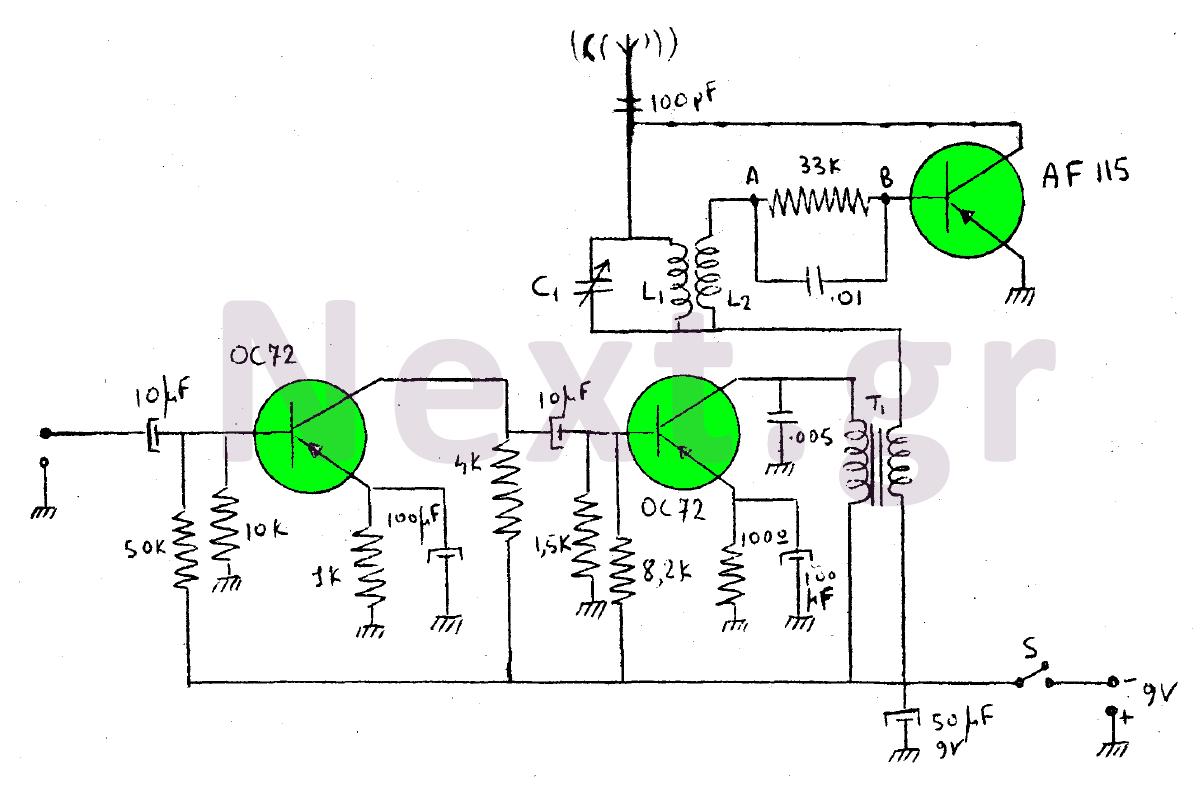
This device is a transmitter operating on medium-wave and short-wave frequencies, utilizing three transistors. The AF115 transistor serves as the oscillator within the circuit. The low-frequency amplifier, consisting of two OC72 transistors, functions as the modulator that generates the...
This SMD FM transmitter operates within a frequency range of approximately 80 to 115 MHz. Under optimal conditions, the signal can be received at a distance of around 200 meters. Although it is classified as low-power, its use may...
Wireless FM Transmitter. The image displays a wireless FM transmitter alongside a pocket radio and a yellow disk for size comparison. When the user speaks into the transmitter, others can hear the transmission on any FM radio. The wireless FM...
Warning: include(partials/cookie-banner.php): Failed to open stream: Permission denied in /var/www/html/nextgr/view-circuit.php on line 713
Warning: include(): Failed opening 'partials/cookie-banner.php' for inclusion (include_path='.:/usr/share/php') in /var/www/html/nextgr/view-circuit.php on line 713