
Fog Lamp Sensor Circuit
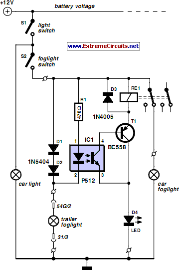
The circuit design for the electronic fog lamp switching mechanism involves several key components that work together to ensure safe operation under foggy conditions. The P521 optocoupler is central to this design, providing electrical isolation between the towing vehicle's fog lamp circuit and the trailer's fog lamp circuit. This isolation is crucial for preventing potential damage to the vehicle's electrical system while ensuring reliable operation.
Diodes D1 and D2 are used to allow current to flow in a controlled manner, ensuring that the correct voltage reaches the optocoupler's LED when the fog lamp in the towing vehicle is activated. The forward voltage drop across these diodes must be accounted for in the circuit design to ensure the optocoupler receives sufficient current to operate effectively.
Transistor T1 acts as a switch that controls the relay. When the optocoupler's photo-transistor conducts, it allows current to flow through T1, which in turn energizes the relay coil. The relay is responsible for interrupting the power supply to the fog lamp of the towing vehicle, thereby preventing any reflections that could impair visibility.
The entire circuit can be compactly assembled on a perforated circuit board, allowing for easy integration into the vehicle's existing electrical system. Proper placement near the rear lamp fitting ensures that the circuit is accessible for maintenance and minimizes the length of wiring runs, which can help reduce potential voltage drops. Careful attention should be paid to the connections and soldering to ensure reliability and durability of the circuit in automotive conditions.
Overall, this electronic solution provides a practical and efficient method for managing fog lamp operation between a towing vehicle and its trailer or caravan, enhancing safety during adverse weather conditions.For several years now, a rear fog lamp has been mandatory for trailers and caravans in order to improve visibility under foggy conditions. When this fog lamp is switched on, the fog lamp of the pulling vehicle must be switched of to avoid irritating reflections.
For this purpose, a mechanical switch is now built into the 13-way female connector in order to switch of the fog lamp of the pulling vehicle and switch on the fog lamp of the trailer or caravan. For anyone who uses a 7-way connector, this switching can also be implemented electronically with the aid of the circuit illustrated here.
Here a type P521 optocoupler detects whether the fog lamp of the caravan or trailer is connected. If the fog lamp is switched on in the car, a current flows through the caravan fog lamp via diodes D1 and D2. This causes the LED in the optocoupler to light up, with the result that the photo-transistor conducts and energies the relay via transistor T1.
The relay switches of the fog lamp of the car. For anyone who`s not all thumbs, this small circuit can easily be built on a small piece of perforated circuit board and then fitted somewhere close to the rear lamp fitting of the pulling vehicle. 🔗 External reference
Related Circuits
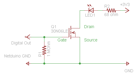
The process of driving an LED involves using a Power MOSFET to control the LED's state (On and Off) via a digital signal. This guide provides a step-by-step approach to wiring the circuit on a breadboard, which serves as...

The operation principle of the proposed metal detector circuit is straightforward yet intriguing. The detection function is activated by sensing a decrease in the quality factor (Q) of the LC network associated with the circuit when a metal object...
The remote control circuit comprises two main components: a transmitter and a receiver. The transmitter circuit is controlled by an NE555 integrated circuit (IC), while the receiver operates based on the frequency of the signal emitted by the transmitter....
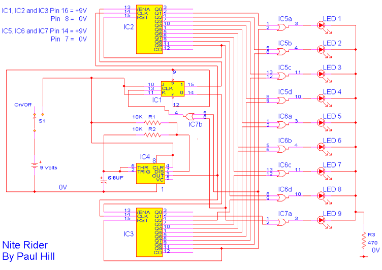
As a cyclist, there is a constant search for methods to enhance visibility during nighttime rides. The concept of the `NITE-RIDER` was developed to create a distinctive and attention-grabbing rear light for bicycles. This design features nine extra-bright LEDs...
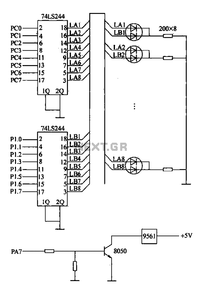
Alarm interface circuitry featuring a two-color light-emitting diode (LED) display. When LAi is at a high level and LBi is low, the green LED lights up; conversely, if LAi is low and LBi is high, the red LED lights...

A simple battery charger circuit with reverse polarity indication is presented. The circuit utilizes the L200 integrated circuit, which is a five-pin variable voltage regulator. It can be powered by DC voltage from either a bridge rectifier or a...
Warning: include(partials/cookie-banner.php): Failed to open stream: Permission denied in /var/www/html/nextgr/view-circuit.php on line 713
Warning: include(): Failed opening 'partials/cookie-banner.php' for inclusion (include_path='.:/usr/share/php') in /var/www/html/nextgr/view-circuit.php on line 713