
Fog Lamp Sensor Circuit
The described circuit provides a solution for managing fog lamp operations between a towing vehicle and a trailer or caravan. The system is designed to ensure that when the rear fog lamp of the trailer or caravan is activated, the corresponding fog lamp on the towing vehicle is automatically deactivated. This is essential for safety, as it reduces glare for other drivers in low-visibility conditions.
The circuit typically employs a relay or a combination of transistors to achieve the desired switching action. When the fog lamp switch on the trailer or caravan is turned on, a signal is sent to the relay, which then interrupts the power supply to the fog lamp of the towing vehicle. Simultaneously, it completes the circuit to power the fog lamp on the trailer or caravan.
In the case of a 7-way connector, the electronic circuit may include additional components such as diodes to prevent back-feeding of current and ensure that the relay operates correctly without interference from other signals in the wiring harness. The circuit can be designed to fit within the existing connector housing, allowing for a seamless integration without requiring significant modifications to the vehicle or trailer's electrical systems.
This electronic solution is advantageous as it provides a more reliable and efficient means of controlling the fog lamp operation compared to mechanical switches, which may wear over time or be subject to environmental factors. The implementation of this circuit can significantly enhance safety during adverse weather conditions, ensuring compliance with regulations while improving overall visibility on the road.For several years now, a rear fog lamp has been mandatory for trailers and caravans in order to improve visibility under foggy conditions. When this fog lamp is switched on, the fog lamp of the pulling vehicle must be switched of to avoid irritating reflections.
For this purpose, a mechanical switch is now built into the 13-way female connector in order to switch of the fog lamp of the pulling vehicle and switch on the fog lamp of the trailer or caravan. For anyone who uses a 7-way connector, this switching can also be implemented electronically with the aid of the circuit illustrated here..
🔗 External reference
Related Circuits

The ECM circuit comprises four sections, as illustrated in the block diagram. A power converter generates a voltage that correlates with the actual real power consumed by the load. This voltage supplies both a bar graph and a voltage-to-pulse...
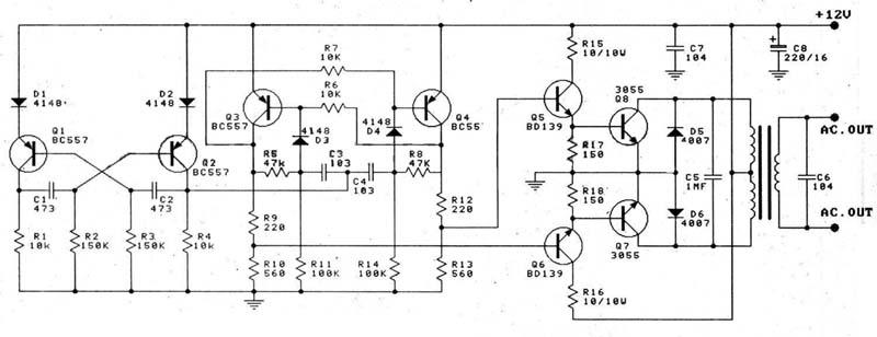
This circuit is a 100W DC inverter based on a transistored multivibrator and serves as a transistor signal amplifier. The inverter converts a 12V DC input voltage to approximately 220V AC. It is recommended to use a 12V car...
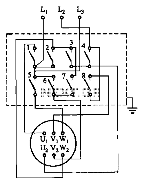
The circuit illustrated in Figure 3-36 includes the starter contact closure detailed in Table 3-1. In the figure, U1, V1, W1, and U2, V2, W2 represent the first three-phase stator windings of the motor terminals. The circuit depicted in Figure...
APM-81 lift includes the main circuit, safety circuit, and brake circuit. The APM-81 lift system is designed with a comprehensive electrical architecture that integrates a main circuit, a safety circuit, and a brake circuit, ensuring reliable operation and enhanced safety...
The high and low voltage cut-off with delay and alarm circuit, along with its circuit diagram, is explained in this post. The high and low voltage cut-off circuit is designed to protect electrical devices from damage caused by excessive voltage...
Second Stage Joule Thief Circuits The second stage Joule Thief circuit is an advanced iteration of the basic Joule Thief design, which is primarily used to extract energy from low-voltage sources, such as depleted batteries. This circuit is particularly effective...
Warning: include(partials/cookie-banner.php): Failed to open stream: Permission denied in /var/www/html/nextgr/view-circuit.php on line 713
Warning: include(): Failed opening 'partials/cookie-banner.php' for inclusion (include_path='.:/usr/share/php') in /var/www/html/nextgr/view-circuit.php on line 713