
Footswitch for Hughes & Kettner Tubemeister

The circuit includes a diode (D1) for reverse polarity protection, ensuring safety if a positive center adapter is mistakenly used instead of a negative center one, or vice versa, depending on the wiring. Resistors R1 and R2, along with capacitor C2, form a voltage divider that supplies the reference voltage for the operational amplifier (op-amp). The values of R1 and R2 do not have to be exactly 47k; any values between 10k and 100k are acceptable as long as they are equal, ensuring a stable divider. Capacitor C1 filters out noise, while capacitor C3 prevents DC leakage into the amplifier. Resistor R3 limits the current to the LED, preventing burnout; a 680-ohm resistor could be used, but a 2.2k resistor is preferred due to availability and common usage for this application. It is recommended to connect pin 7 (the output for the second side of the op-amp) of the TL072 to ground, as it will not be utilized in this circuit.
This circuit fits well within a 1590A enclosure, provided the layout is appropriately designed. The original layout was larger but was later redesigned to be more compact, allowing additional space within the enclosure for other components.
Parts:
R1: 47k
R2: 47k
R3: 2.2k
R4: 1M
C1: 100nF
C2: 10uF
C3: 10uF
D1: 1N4001
D2: 3mm LED
U1: TL072
The circuit is designed for use in audio applications, particularly in pedal formats. The 3PDT toggle switches allow for versatile routing options, enabling the user to toggle between different effects or signal paths. The momentary footswitch provides a means for temporary activation, suitable for effects that are only needed during specific passages of performance. The 4DPT footswitch can manage multiple functions or signal paths simultaneously, enhancing the flexibility of the pedal.
The use of the TL072 operational amplifier is notable for its low noise and high-performance characteristics, making it suitable for audio applications where signal integrity is paramount. The combination of capacitors and resistors ensures that the circuit operates smoothly, preventing unwanted noise and ensuring stable operation under varying conditions.
The compact design of the circuit is advantageous for portability, allowing musicians to integrate it into their pedalboards without taking up excessive space. The choice of components reflects a balance between availability and performance, ensuring that the circuit can be easily assembled while maintaining high functionality. Overall, this circuit serves as a reliable component for audio effects, suitable for both amateur and professional use.It uses 3 x 3PDT toggle switches, a momentary soft touch SPST footswitch switch and a 4DPT footswitch, which are not rare components, but certainly not as readily available as most pedal parts. In reality it is a bit too small for large feet stomping it on stage – there’s a real potential of stomping the wrong thing.
So, here’s the circuit I used to create the 072 with. It is pretty much as basic as you can get, especially as it is always on but it is very effective at its job.
D1 is for reverse polarity protection incase people use a positive center adaptor instead of negative center (or vice versa depending how you wire it). R1, R2 and C2 form the voltage divider which provides the reference voltage for the opamp. R1 and R2 don’t have to be 47k, they can be anything (I would stick between 10k and 100k though to ensure the divider is reasonably stable) as long as the values are equal.
C1 helps prevent any noise while C3 prevents and DC from the circuit leaking into the amp and R3 limits the current so the LED doesn’t burn out. You could get away with something like a 680r resistor for R3, but the I like the 2.2k because I have a load of them, and they are commonly used for this purpose!
I would hook up pin 7 (the output for the second side of the opamp) of the TL072 to ground as it isn’t going to be used.
And that is really all there is too it. Fits nicely in the 1590A enclosures, providing your layout fits. On the only 072 I have built I had quite a big vero layout and it still fit, but I redesigned it after to be that bit smaller to allow slightly more room in the enclosure for everything else.
Parts:
R1 47k
R2 47k
R3 2.2k
R4 1M
C1 100nF
C2 10uF
C3 10uF
D1 1N4001
D2 3mm LED
U1 TL072
🔗 External reference
Related Circuits
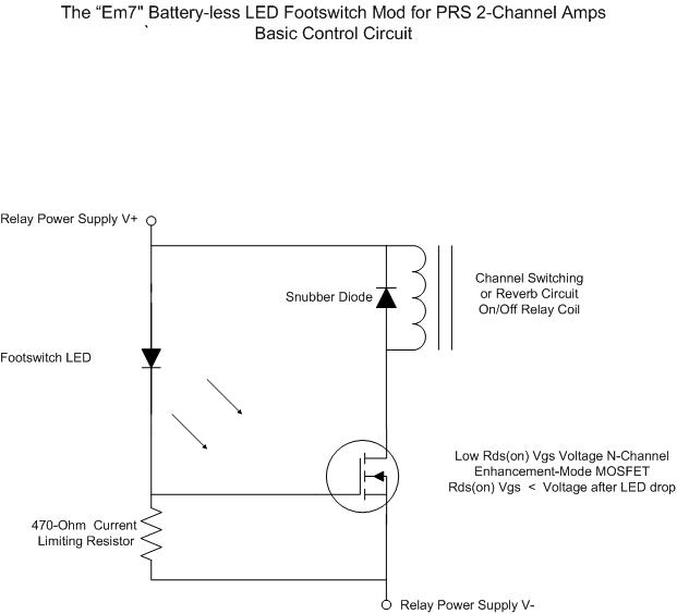
For individuals seeking LED-based footswitching without the inconvenience of battery installation, a battery-less LED-based footswitch modification is being developed for 2-channel amplifiers. This solution is designed to work with the existing TRS jack and footswitch, and it will involve...
Warning: include(partials/cookie-banner.php): Failed to open stream: Permission denied in /var/www/html/nextgr/view-circuit.php on line 713
Warning: include(): Failed opening 'partials/cookie-banner.php' for inclusion (include_path='.:/usr/share/php') in /var/www/html/nextgr/view-circuit.php on line 713