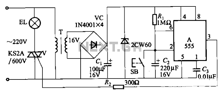
for the lights to flash

The circuit utilizes a 555 timer integrated circuit (IC) configured as an astable multivibrator. The flashing rate can be adjusted from very fast to a maximum of once every 1.5 seconds by changing the setting of the preset variable resistor VR1.
The 555 timer IC is a versatile device commonly used in various timing applications. In the astable mode, it operates continuously, generating a square wave output. The frequency of this output is determined by two resistors (R1 and R2) and a capacitor (C1) connected to the timing pins of the IC.
In this specific circuit, VR1 serves as a variable resistor that allows the user to adjust the resistance in the timing network, thereby altering the charging and discharging times of the capacitor. This control over the timing components results in a modulation of the flashing rate of an LED or any other connected load.
The frequency (f) of the oscillation can be calculated using the formula:
f = 1.44 / ((R1 + 2 * VR1) * C1)
Where:
- R1 is a fixed resistor,
- VR1 is the variable resistor, and
- C1 is the timing capacitor.
By selecting appropriate values for R1, C1, and the range of VR1, the designer can achieve a wide range of flashing rates, from rapid blinking to a slower pulse of up to once every 1.5 seconds. The output from the 555 timer can be used to drive an LED directly if the current requirements are within the specifications of the IC, or it can be interfaced with a transistor to control higher power loads.
In summary, this circuit serves as an effective and adjustable flashing light system, leveraging the capabilities of the 555 timer IC in its astable configuration to meet varying operational needs.Circuit uses a 555 timer IC working as an astable multivibrator. The flashing rate can be varied from very fast to a maximum of once in 1. 5 sec by varying the preset VR1. 🔗 External reference
Warning: include(partials/cookie-banner.php): Failed to open stream: Permission denied in /var/www/html/nextgr/view-circuit.php on line 713
Warning: include(): Failed opening 'partials/cookie-banner.php' for inclusion (include_path='.:/usr/share/php') in /var/www/html/nextgr/view-circuit.php on line 713


