
Free 8052 Microcontroller Based Projects

In this context, a method for sending data to a microcontroller and receiving a response is outlined. For demonstration purposes, the focus is on controlling an LED connected to port P2.0. A communication protocol is established, where an ASCII 255 is sent as a synchronization byte, followed by the on/off state (0 or 1). The microcontroller is designed to wait for two bytes of data; upon receiving this data, it will either activate or deactivate the LED. The setup involves configuring a Visual Basic (VB) project where the user selects a pin state via option buttons and clicks a command button to transmit data to the microcontroller. The MSComm control is initialized, and code is added to facilitate the interaction. When the VB project is executed, selecting either the ON or OFF option and pressing send results in the LED turning ON or OFF accordingly.
The electronic circuit for the personal safe utilizes a microcontroller equipped with fingerprint recognition capabilities. The system includes a fingerprint sensor, which captures and processes the biometric data of authorized users. The microcontroller is programmed to manage the storage and verification of fingerprints, ensuring that only registered fingerprints can unlock the safe.
The circuit comprises the following key components:
1. **Microcontroller**: This serves as the brain of the personal safe, processing input from the fingerprint sensor and controlling the locking mechanism.
2. **Fingerprint Sensor**: A biometric device that captures fingerprint images and converts them into digital templates for storage and comparison.
3. **Locking Mechanism**: An electronic lock that is controlled by the microcontroller. When a valid fingerprint is recognized, the microcontroller activates the locking mechanism to allow access.
4. **Power Supply**: A reliable power source, typically a battery or a DC power adapter, ensures that the system remains operational, even during power outages.
5. **User Interface**: A set of buttons or a touchscreen interface that allows users to manage fingerprint data, including adding, deleting, and verifying fingerprints.
6. **LED Indicators**: Visual indicators that provide feedback on the status of the safe, such as power status, fingerprint verification success, or failure.
This configuration not only enhances security through biometric authentication but also simplifies user interaction by eliminating traditional keys and combinations. The communication protocol established for controlling the LED can be adapted for other functionalities, such as signaling alerts or status updates regarding the safe's operation. This comprehensive approach ensures a high level of security while maintaining ease of use for authorized individuals.Personal Safes are revolutionary locking storage cases that open with just the touch of your finger. These products are designed as "access denial" secure storage for medications, jewelry, weapons, documents, and other valuable or potentially harmful items. These utilize fingerprint recognition technology to allow access to only those whose fingerp rints you choose. It contains all the necessary electronics to allow you to store, delete, and verify fingerprints with just the touch of a button. Stored fingerprints are retained even in the event of complete power failure or battery drain. These eliminates the need for keeping track of keys or remembering a combination password, or PIN. It can only be opened when an authorized user is present, since there are no keys or combinations to be copied or stolen, or locks that can be picked.
k eeping track of keys or remembering a combination password, or PIN. It can only be opened when an authorized user is present, since there are no keys or combinations to be copied or stolen, or locks that can be picked. In this article we are going to learn how to send data to a microcontroller and make the microcontroller respond to the data.
For simplicity we are just going to send data to turn on and off an LED which is connected at port P2. 0. So lets start off with designing a communications protocol. From VB we will send an ASCII 255, as a synch byte, and the on/off state (0 or 1). The microcontroller will wait for two (2) bytes of data. After these two bytes of data are received, it will then either switch on/off the LED Now that the form is set up and ready to go, we need to start adding our code to the project.
The user will select a pin state from option button, and then click cmdSend to send the data to the microcontroller. So first of all we need to set up the MSComm control, and select one of the pin states to start with.
So lets add the following code to our form. Now run the VB project, select either ON or OFF, and press send. You should see the LED turn ON when you send a ON command, and turn OFF when you send a OFF command. 🔗 External reference
Related Circuits
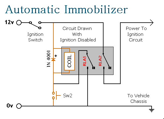
This circuit features automatic exit and entry delays, an optional instant alarm zone, an optional intermittent siren output, and an automatic reset. By adding external relays, the vehicle can be immobilized and the lights can be flashed. The alarm...
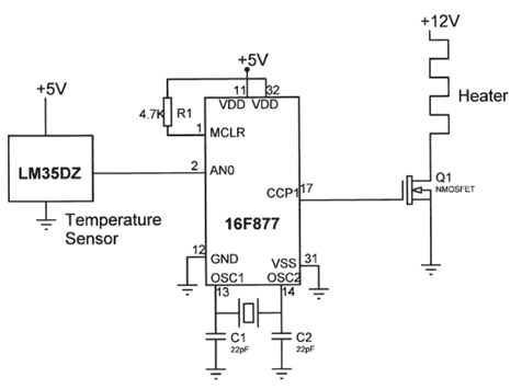
The electrical circuit diagram of this temperature control circuit consists of a 3-pin analog temperature sensor (LM35DZ), a built-in A/D converter microcontroller (PIC16F877), and the heater driver (IRL1004). The temperature control circuit utilizes the LM35DZ, a precision analog temperature sensor...
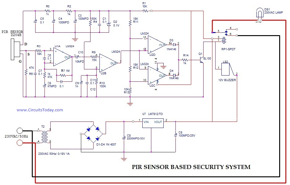
PIR (Passive Infrared Radial) Sensor-Based Security System, circuit diagram, working, applications. The PIR (Passive Infrared) sensor-based security system is designed to detect motion by measuring changes in infrared radiation emitted by objects in its vicinity, particularly warm bodies such as...

After learning to operate the device, it became evident that inertia posed a significant challenge. The constructed system is notably heavy, making it difficult to initiate motor operation at full speed. Despite having some understanding of physics, practical experience...
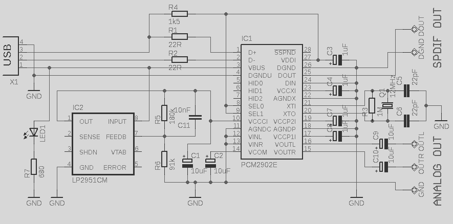
This circuit is a quality preamplifier with a built-in USB DAC designed for the Leachamp power amplifier. The schematic is based on the PCM2902 datasheet. The circuit includes a DAC and ADC, SPDIF input and output, and features three...

This project originated as an effort to create an inexpensive phono stage for an old turntable equipped with a low-cost cartridge using available components. However, it evolved into a noteworthy project that significantly enhances the overall analog setup. The...