
Frequency-boundary-detector
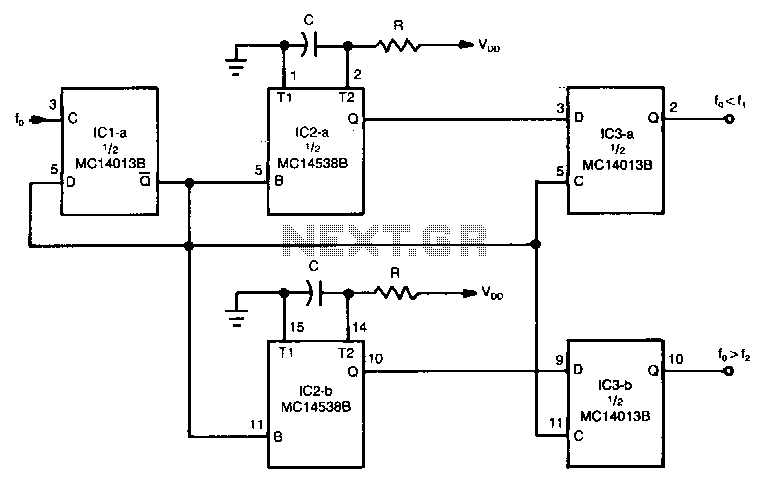
The circuit can be used to determine whether an input signal falls within a specific frequency range. The device comprises three integrated circuits (ICs), including a dual monostable multivibrator and two dual D-type flip-flops. The signal whose frequency is being analyzed is connected to the clock input of one of the flip-flops. The Q output of this flip-flop (IC1a) is cross-coupled to its data input, functioning as a divide-by-two counter. The trailing edge of the Q output triggers the one-shot circuits formed by IC2. The upper and lower frequency boundaries are established by the two sections of IC2, the dual precision monostable multivibrator, along with their external resistor-capacitor (RC) networks. The upper frequency boundary, f1, is determined by the output of IC2a, while the lower frequency boundary, f2, is set by the output of IC2b. The frequency of the input signal can range from DC to 100 kHz. The states of the outputs from IC2, which define the upper and lower frequency boundaries, are latched by IC3a and IC3b, respectively. The output of IC3a will be high only when the input frequency is lower than the output of IC2a, f1. Conversely, the output of IC3b will be high only when the input frequency exceeds the output of IC2b, f2.
The circuit operates by utilizing the properties of the flip-flops and the monostable multivibrator to monitor and compare frequency inputs. The first flip-flop (IC1a) effectively halves the frequency of the incoming signal, which aids in the processing of the signal for frequency comparison. The outputs from the monostable multivibrator (IC2) are critical for defining the operational thresholds of the circuit. By adjusting the external RC components connected to IC2, the upper and lower frequency limits can be finely tuned to meet specific application requirements.
The dual monostable multivibrator generates precise timing intervals that are essential for establishing the frequency boundaries. These intervals are determined by the RC time constants, which can be calculated using the formula T = 1.1 * R * C for the monostable configuration. This allows for flexibility in setting the desired frequency thresholds in a range suitable for various applications.
Furthermore, the outputs from IC2 are latched by IC3a and IC3b, which are responsible for providing a stable output state that indicates whether the input frequency is within the specified range. The latch mechanism ensures that once a condition is met (either above or below the defined frequency limits), the output remains stable until the circuit is reset or the input signal changes.
Overall, this circuit design is highly effective for frequency detection and can be utilized in various applications, such as signal processing, frequency modulation detection, and other electronic communication systems where frequency monitoring is essential.The circuit can be used to tell whether or not an input signal is within a certain frequency range. The device consists of three !Cs, a dual monostable multivibrator, and two dual D-type flip-flops. The signal whose frequency is in question is fed to the clock input of one of the flip-flops. The Q output of that flipflop (IC1a) is cross coupled to its data input so that it acts like a divide-by-two counter. The trailing edge of the Q output is used to trigger the one shots formed by IC2. The upper-and lower-frequency boundaries are determined by the two sections of IC2; the dual precision monostable multivibrator and their external rc networks. The upper-frequency boundary, fl, is set by the output of IC2a, and the lower-frequency boundary, f2, is set by the output of IC2b.
The frequency of the input to the circuit can be anywhere from de to 100kHz. The states of the outputs of IC2, which determine the upper-and lower-frequency boundaries, are latched by IC3a and IC3b respectively. The output of IC3a will be high only when the input frequency is less than that of the output of IC2a, j 1.
The output of IC3b will be high only when the frequency of the input is greater than that of the output of IC2b, f2. 🔗 External reference