
Frequency Counter Circuit using Micro Controller

The frequency meter circuit is designed to measure the frequency of input signals and display the results on an LCD screen. The core of the circuit is the AVR microcontroller, which processes the input signal and performs the necessary calculations to determine the frequency.
The circuit typically includes an input stage where the signal is conditioned, often using a buffer or amplifier to ensure compatibility with the microcontroller's input requirements. This input stage may also involve filtering to eliminate noise, allowing for more accurate frequency measurements.
Once the signal is conditioned, the microcontroller utilizes an internal timer to count the number of cycles of the input signal over a defined period. This time period can be adjusted based on the desired resolution of the frequency measurement. The resulting count is then converted into a frequency value using the formula: Frequency = Count / Time Period.
The processed frequency value is sent to the LCD display, which is interfaced with the microcontroller. The display is typically a 16x2 or 20x4 character LCD, which provides a clear readout of the measured frequency in hertz (Hz). The microcontroller may also be programmed to handle various display formats, such as switching between different units (e.g., kilohertz or megahertz) or displaying additional information like signal amplitude.
The embedded C code for the AVR microcontroller handles the initialization of the LCD, the input signal processing, and the timing operations. Proper coding practices ensure efficient use of the microcontroller's resources, allowing for accurate and responsive frequency measurements.
Overall, this frequency meter circuit is a valuable tool for electronics enthusiasts and professionals alike, providing a practical application of microcontroller technology in signal measurement.Simple frequency meter or frequency counter circuit with LCD display and Avr micro controller.DIY schematic circuit diagram & embedded c code.. 🔗 External reference
Related Circuits
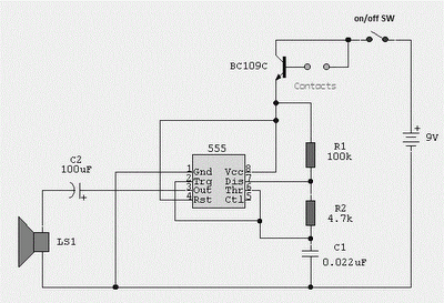
Probes or contacts may utilize a non-reactive metal. Gold or silver plated contacts from an old relay may be used; however, a cost-effective alternative is to wire alternate copper strips from a piece of veroboard. These will eventually oxidize,...
The display interface utilizes the ICM7218A/B in conjunction with an 8048 family microcontroller. An 8-bit data bus (DBO/DB7-IDO/ID7) facilitates the transfer of control and data information to the 7218 display interface during successive WRITE pulses. The mode input pins...
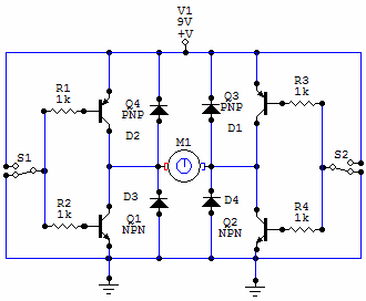
You have 4 transistors, wired as ON OFF switches. Two signal lines allow you to run the motor in one direction, when reversed, the motor runs in the other direction. It's very straightforward to use and build, but be...
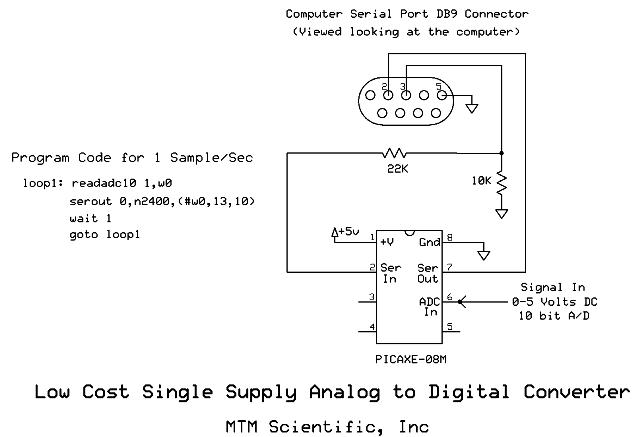
Collecting and storing experimental data presents a common challenge for hobbyists. A widely used method involves utilizing a device that converts analog data into digital format and stores the information on a computer. These devices are known as A/D...
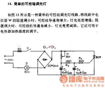
A simple silicon-controlled rectifier (SCR) dimmer circuit is depicted in Figure 13. This circuit is designed to control the brightness of lights. As the resistance in the potentiometer decreases, the conduction angle of the SCR increases, resulting in an...
Deep discharge of a battery can lead to plate curing, which shortens the battery's lifespan. To prevent this, a discharge protection device can be implemented. The circuit diagram illustrates this mechanism. When the battery voltage falls to a predetermined...
Warning: include(partials/cookie-banner.php): Failed to open stream: Permission denied in /var/www/html/nextgr/view-circuit.php on line 713
Warning: include(): Failed opening 'partials/cookie-banner.php' for inclusion (include_path='.:/usr/share/php') in /var/www/html/nextgr/view-circuit.php on line 713