
Frequency counter Logic schematic
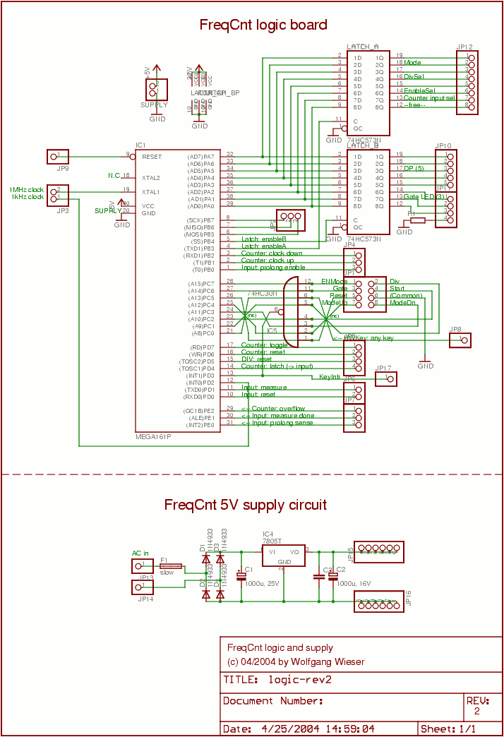
The schematic illustrates a bidirectional rectifier circuit that is essential for converting alternating current (AC) to direct current (DC), ensuring that the voltage regulator can function effectively. The 7805 voltage regulator is a popular choice for providing a fixed output voltage of 5V, which is crucial for the stable operation of digital circuits. The inclusion of capacitors in the circuit serves to filter any voltage fluctuations, thereby enhancing the reliability of the power supply.
The ATMega161 microcontroller serves as the central processing unit for the frequency counter, managing data acquisition and processing tasks. Its connections to other boards via cables facilitate communication and control among various components, ensuring that the system operates cohesively. The use of a 9-pin SUB-D service port for connecting JP9 and JP2 allows for easy access to reset and SPI communication functionalities, which are critical for programming and debugging the microcontroller.
The design flaw associated with the HC30 gate highlights the importance of thorough testing and validation in circuit design. The decision to utilize unconventional wire connections around this component indicates a pragmatic approach to overcoming layout challenges and ensuring signal integrity on the PCB.
In addition, the HC753 octal transparent latches are integral to the system, as they temporarily store the state of the front panel LEDs, allowing for visual feedback to the user. This feature enhances user interaction and provides a clear indication of the system's status. The front panel keys connected through JP1 enable user input, facilitating control over the frequency counter's operations.
Overall, the schematic effectively combines power management, microcontroller interfacing, and user interaction components, creating a robust design suitable for frequency counting applications. The detailed connections and components are crucial for ensuring the functionality and reliability of the entire system.The lower schematic is a pretty standard bidirectional rectifier together with capacitors and a 7805 as a fixed 5V source which supplies all the electronic in the frequency counter. For "security reasons" a fuse is used. The upper diagram shows the main microcontroller, an ATMega161, connected to all the other boards via various cables.
JP9 (reset ) and JP2 (SPI) are connected to the 9pin SUB-D service port at the back side. The large gate HC30 turned out to be a design flaw and was not mounted into the socket. The strange wire connections around it are due to ease signal routing on the PCB. The HC753 octal transparent latches save the current LED status of most LEDs on the front panel. The keys on the front panel are connected via JP1. The other connectors are well described in the schematic. 🔗 External reference
Related Circuits
A PLL oscillator, or phase-locked loop oscillator, is a control method that compares a controlled system or plant to a reference signal. A phase-locked loop (PLL) oscillator is a sophisticated electronic circuit designed to synchronize an output signal's phase and...
Below is the final schematic for the Menta ECG Simulator project. LadyAda's Eagle schematic for the Menta was used as a starting point. The Menta ECG Simulator project is designed to emulate the electrical signals produced by the heart, providing...
Essentially, this is a Hartley oscillator utilizing a triple-emitter follower, suitable for audio and low radio frequencies. The frequency is determined by the components, and at 1 kHz, a typical capacitor value would be 4.7 µF tantalum, although this...

A very high-power amplifier with 10 pairs of power transistors. It can utilize MJ15024 and MJ15025 or MJ21193 and MJ21194. These 20 transistors function as the final active components. The design is based on four integrated circuits: TL072, TL074,...
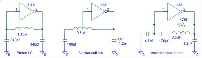
This oscillator does not require biasing components. Only an inductor and various matching or tuning capacitors are needed to set the operating frequency. The active component is the 74HCU04 hex inverter, with only one of the six inverters necessary...
The RF design and construction of radio frequency oscillators. Radio frequency (RF) oscillators are essential components in various electronic systems, generating signals at specific frequencies used for communication, signal processing, and other applications. The design of RF oscillators involves several...
Warning: include(partials/cookie-banner.php): Failed to open stream: Permission denied in /var/www/html/nextgr/view-circuit.php on line 713
Warning: include(): Failed opening 'partials/cookie-banner.php' for inclusion (include_path='.:/usr/share/php') in /var/www/html/nextgr/view-circuit.php on line 713