
Frequency-counter-preamp
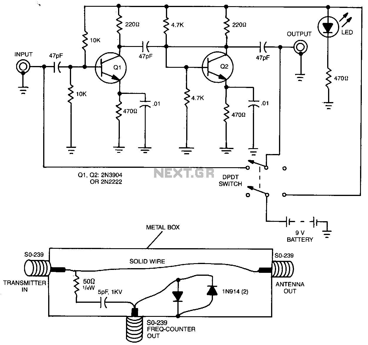
The preamplifier, when utilized with a short length of shielded cable and clip leads, allows signals that typically do not produce a readout to generate precise and stable readings on the counter. A DPDT switch is incorporated to bypass the circuit when amplification is unnecessary. Additionally, the preamplifier can serve multiple purposes; for instance, it was tested as a receiver preamplifier, enhancing received signal strength by approximately 6 S-units at 30 MHz. A line tap can be employed to measure the frequency directly at the output of a transmitter. This circuit comprises two diodes, one resistor, and one capacitor. The line tap effectively captures a low-amplitude signal for measurement by the frequency counter and can be connected to transmitters with output power ranging from 1 to 250 W.
The described preamplifier circuit serves a critical role in enhancing weak signals for accurate measurement and analysis. It features a compact design, utilizing shielded cables to minimize noise interference, which is essential in high-frequency applications. The incorporation of clip leads allows for easy connections to various test points, ensuring versatility in different setups.
The DPDT (Double Pole Double Throw) switch is a key component, providing the user with the flexibility to bypass the amplification stage when it is not required, thus preserving the integrity of the signal and preventing unnecessary amplification of noise. This feature is particularly useful in scenarios where the input signal is already at a sufficient level for direct measurement.
The preamplifier's capability as a receiver preamplifier is noteworthy, as it significantly boosts the signal strength by 6 S-units at 30 MHz. This enhancement is crucial in applications such as radio communications, where weak signals must be amplified for reliable reception. The improvement in signal strength can lead to better clarity and reduced error rates in data transmission.
Furthermore, the line tap circuit, consisting of two diodes, a resistor, and a capacitor, is designed to measure the frequency output of transmitters effectively. This simple yet efficient circuit allows for the extraction of low-amplitude signals, which can be accurately measured by a frequency counter. The ability to connect to transmitters with output powers between 1 and 250 W makes this setup suitable for a wide range of applications, from amateur radio to professional broadcasting.
In summary, the combination of the preamplifier and line tap circuit provides a robust solution for enhancing signal measurement and analysis, making it an invaluable tool in electronic testing and communication systems.By using the preamplifier with a short length of shielded cable and clip leads, signals that generally could not generate a readout, generate precise and stable readouts on the counter. The DPDT switch is used to bypass the circuit when amplification is not needed. The preamplifier can also be used for other purposes. For example, the unit was also tested as a receiver preamplifier and increased received signal strength about 6 S-units at 30 MHz.
A line tap can be used to measure the frequency directly at the output of a transmitter. The entire circuit for that consists of two diodes, one resistor, and one capacitor. The line tap simply picks a low-amplitude signal for measurement by the frequency counter. The tap can be connected to transmitters with an output power of between 1 and 250 W. 🔗 External reference