
FREQUENCY COUNTER PREAMP
The described preamplifier circuit utilizes the LM733 or NE592 operational amplifiers, which are known for their high-speed performance and low noise characteristics. The bandwidth of 100 MHz indicates that the circuit is capable of amplifying signals with frequencies up to this limit, making it suitable for applications in high-frequency signal processing.
The FET (Field Effect Transistor) inputs are a critical component of this preamp, providing a very high input impedance of around 1 MΩ. This high input impedance is essential for minimizing loading effects on the signal source, ensuring that the original signal is preserved without significant attenuation or distortion.
Signal conditioning is performed by transistors Q4 and Q5, along with IC2. These components work together to enhance the signal's quality by reducing noise and improving linearity. Q4 and Q5 may be configured as part of a differential amplifier stage, allowing for common-mode rejection and further enhancing the circuit's ability to process weak signals in the presence of noise.
The overall design of the preamplifier is aimed at maintaining signal integrity while providing the necessary gain and bandwidth for applications in audio processing, RF communications, or other high-frequency electronic systems. The careful selection of components and their configuration plays a crucial role in achieving the desired performance metrics of the preamp.Based on the LM733 or NE592, the preamp shown has a bandwidth of 100 MHz. The FET inputs provide about 1-M © input impedance. Q4, Q5, and IC2 provide signal conditioning. 🔗 External reference
Related Circuits
This circuit illustrates the configuration of an ICM7217 and an ICM7555 designed as a basic frequency counter. The connections between the ICM7217 and a common-cathode LED display are depicted in Figure 12-18. Calibration of the frequency counter is accomplished...
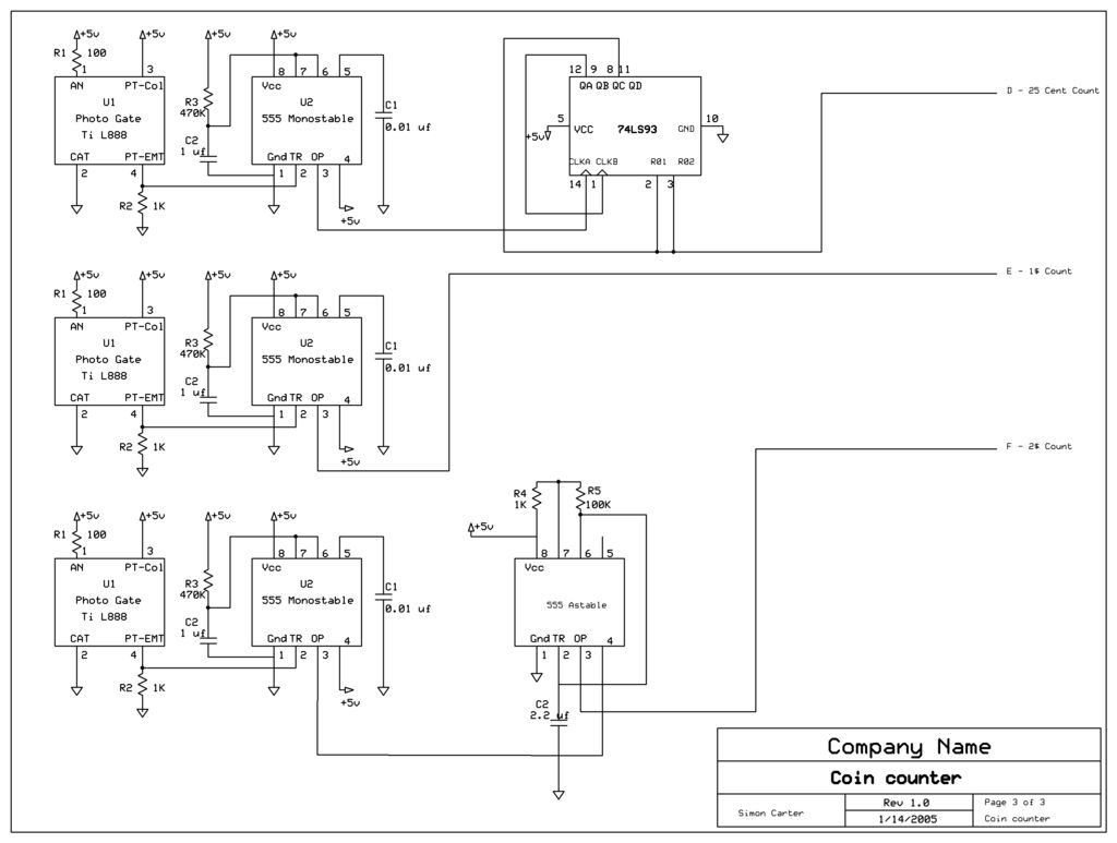
The next counter section operates similarly but is designed to count four quarters, single $1 coins (loonies), and single $2 coins (toonies). The circuit for the toonies is configured. The circuit for the counter section includes a digital counting mechanism...
This circuit measures the distance covered during a walk. Hardware is located in a small box slipped in pants' pocket and the display is conceived in the following manner: the leftmost display D2 (the most significant digit) shows 0...
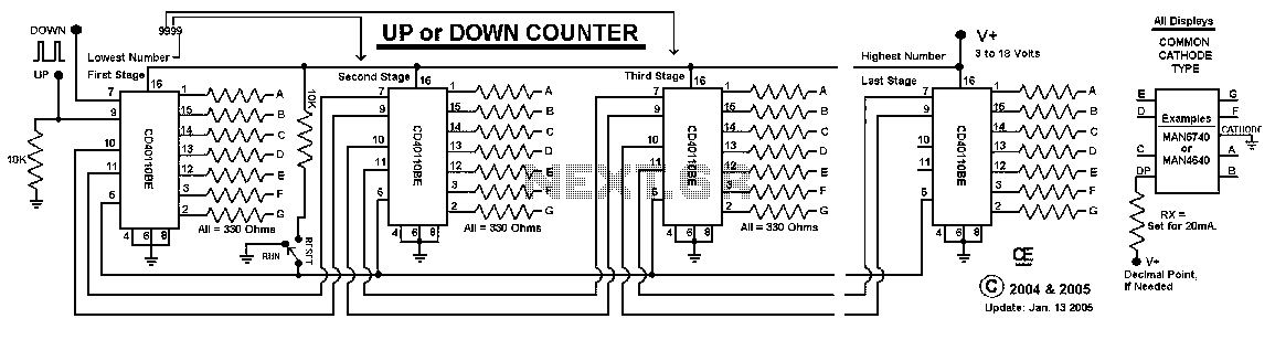
This Circuit uses a CD40110BE, Up/Down Counter IC's. This IC is able to Source Each Segment with 25 mA, Giving a Very Nice Bright Display. The 7 Segment Displays MUST be a Common Cathode Type, as I have used...
The TA2003PG and TA2003FG are integrated circuits designed for AM/FM radio applications. These ICs facilitate AM/FM radio functionality, including FM front-end and AM/FM intermediate frequency processing. When combined with the TA7368P mono power amplifier IC, a comprehensive AM/FM radio...

This circuit measures the distance covered during a walk. The hardware is housed in a small box that can be slipped into a pants pocket, with the display designed as follows: the leftmost display D2 (the most significant digit)...