
Frequency-detecting-comparator
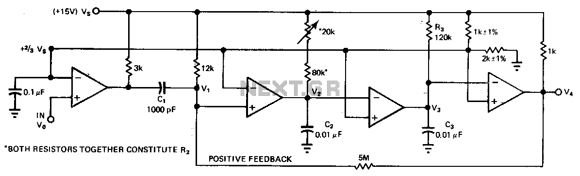
A quad comparator serves as the foundation for a frequency detector that is both faster and more cost-effective than more complex alternatives utilizing frequency-to-voltage converter chips. Positive feedback through a 5 MΩ resistor enables the circuit to detect changes as small as two percent, with the output responding to these changes in approximately one cycle. When the input frequency is high, V is pulled low and is not permitted to exceed 2.13 V. Conversely, when the input frequency falls below the threshold, V exceeds 2.13 V once per cycle, but 1-3 is kept below this limit. The trip frequency is characterized by the equation F = 1/(1.1 R2 C2). R2 can be adjusted to allow for fine-tuning of the trip point, while the value of R3 must remain greater than R2.
The described frequency detector leverages a quad comparator, which is an integrated circuit that contains four independent, high-gain, frequency-compensated comparators. This design is advantageous for applications requiring rapid response times and cost efficiency. The use of positive feedback through a 5 MΩ resistor enhances the circuit's sensitivity, allowing it to detect minute fluctuations in input frequency, specifically those changes as small as two percent.
The output behavior of the circuit is dictated by the input frequency. At higher frequencies, the output voltage, V, is actively pulled low, ensuring it does not exceed the specified limit of 2.13 V. This characteristic is crucial for maintaining stable operation in high-frequency environments. In contrast, when the input frequency drops below the defined threshold, the output voltage exceeds 2.13 V once per cycle, while the signal 1-3 remains constrained below the 2.13 V limit, thereby preventing erroneous triggering.
The trip frequency, which is the frequency at which the comparator switches states, is defined mathematically by the equation F = 1/(1.1 R2 C2). This relationship indicates that the trip frequency is inversely proportional to the product of the resistance R2 and the capacitance C2, multiplied by a constant factor of 1.1. The ability to adjust R2 allows for precise trimming of the trip point, enabling the circuit to be tailored for specific applications. However, it is essential to maintain R3 at a value greater than R2 to ensure proper functionality and stability of the circuit.
Overall, this frequency detector design is an efficient solution for applications requiring fast frequency detection with minimal component complexity, making it an attractive option for various electronic systems.A quad comparator forms the basis of a frequency detector that is faster and less expensive than more complex versions designed around frequency-to-voltage converter chips. Positive feedback through a 5MO resistor allows the circuit to resolve changes as small as two percent; the output responds to those changes in about one cycle.
When the input frequency is high, V, is pulled low; it"s never allowed to exceed 213 V. When the input frequency is lower than the limit, V, exceeds 213 V once each cycle, but 1-"3 is held below that limit. The trip frequency is defined by F = 1/(1.1R2C2). R2 can be adjusted to permit trimming of the trip point, but the value of R3 must remain larger than R2. 🔗 External reference
Warning: include(partials/cookie-banner.php): Failed to open stream: Permission denied in /var/www/html/nextgr/view-circuit.php on line 713
Warning: include(): Failed opening 'partials/cookie-banner.php' for inclusion (include_path='.:/usr/share/php') in /var/www/html/nextgr/view-circuit.php on line 713