
frequency multiplier for lf
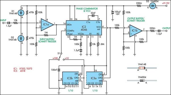
The circuit design for the frequency multiplier is based on the integration of a phase-locked loop (PLL) and a dual divide-by-10 counter, which enhances measurement accuracy for low-frequency signals. The 4046 PLL serves as the core component, providing frequency multiplication capabilities while maintaining phase coherence. The input signal from the audio oscillator is conditioned through a comparator (IC1a) to ensure a clean square wave is fed to the PLL.
Upon receiving the input signal at its SIGin pin, the PLL generates an output frequency that is a multiple of the input frequency. The output is then routed to the 4518 counter (IC3), which divides the frequency based on the user-selected multiplication factor via switch S1. The design allows for two modes of operation: multiplying the input frequency by 10 or by 100. The divided output is then fed back into the PLL's COMPin, effectively closing the loop and stabilizing the multiplied frequency for accurate measurement.
This configuration is particularly beneficial for applications involving bass reflex loudspeaker cabinets, where precise resonance frequency measurement is crucial. The limitation of the 4046's operational frequency (up to 20kHz) necessitates careful consideration of input signal frequencies, but the design remains effective for the intended application range.
Overall, this circuit not only addresses the inherent inaccuracies of low-frequency measurements but also provides a robust solution for audio engineers and designers who require reliable frequency analysis in the development of high-fidelity audio systems.When designing bass reflex loudspeaker cabinets, it is necessary to measure the resonance of the speaker to an accuracy of about 1%. To do this, you need an audio oscillator and a frequency counter. However, the typical accuracy and resolution of a frequency counter when measuring frequencies below 50Hz can lead to errors of several percent.
The s olution to this problem is to use a frequency multiplier and the circuit presented here can be switched to multiply by 10 or 100. It uses a 4046 phase locked loop (PLL) and a 4518 connected as a dual divide-by-10 counter. As shown, the oscillator signal is fed into the comparator formed by IC1a and its output drives the SIGin input, pin 14, of the 4046 PLL (IC2).
The PLL`s output is fed to IC3 and divided by 10 or 100, depending on the setting of switch S1. The divided signal is then fed to the COMPin input (pin 3) of IC2. In this way, the PLL is forced to multiply the input frequency by 10 or 100 and this multiplied frequency can be read out with much improved accuracy by a typical digital frequency meter. However, you must then divide the displayed reading by the selected multiplication ratio to get the true frequency.
The limitation in this circuit is that the 4046 can only run up to 20kHz so that the input frequency is limited to 200Hz or 2kHz, depending on the multiplication ratio. This is quite adequate for measuring bass reflex cabinets. 🔗 External reference
Related Circuits
This frequency doubler using a single 4069 hex inverter IC, a frequency doubler can be constructed to give an output pulse train whose frequency is twice that of a squarewave input signal. The signal is applied to the input...
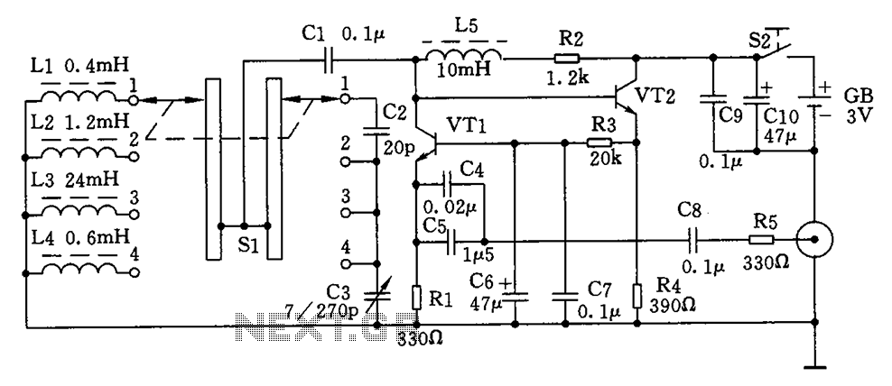
This is a simple high-frequency signal generator. By changing the inductance of the LC resonant circuit using the band switch S1, the high-frequency oscillation frequency range can be altered. The generator is divided into four frequency stages: the first...
An equalizer is a passive or active electronic component or circuit, such as tone control, designed to modify or flatten the frequency response characteristics of a system. The NE5532 is a low-noise, dual operational amplifier that features full power...
A simple variable frequency oscillator utilizing a 555 timer IC to generate a square wave frequency that can be adjusted using a potentiometer. The circuit operates primarily on the principles of astable multivibrator configuration using the 555 timer IC, which...
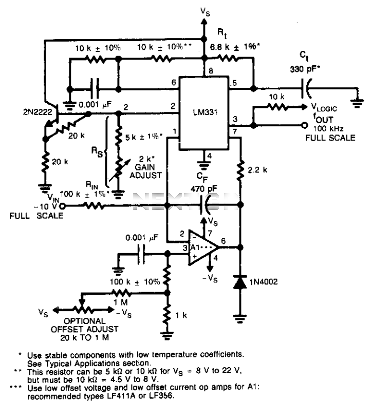
This circuit utilizes a conventional operational amplifier in conjunction with a feedback capacitor (CF) to perform integration. When the output of the integrator exceeds the nominal threshold level at pin 6 of the LM131, it triggers the timing cycle....
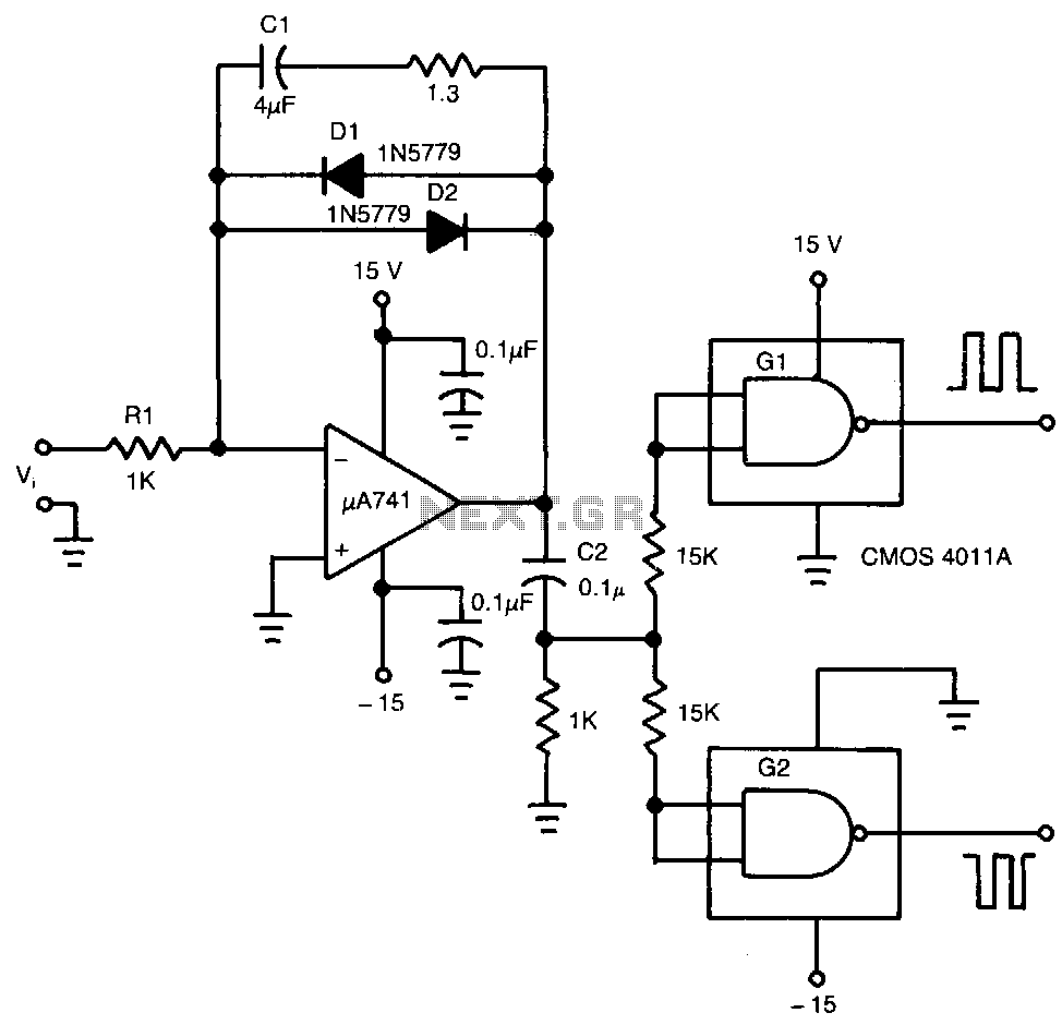
The input voltage, V1, causes capacitor C1 to charge, producing a ramp voltage at the output of the 741 operational amplifier. Diodes D1 and D2 are four-layer devices. When the voltage across C1 reaches the breakover voltage of either...