
Frequency Shift Keying (FSK) Encoding and Decoding
Frequency Shift Keying (FSK) is a digital modulation technique that encodes data by varying the frequency of a carrier signal. In a typical FSK system, two distinct frequencies are used to represent binary digits (bits). The TC9400 V/F converter plays a crucial role in this process by generating the required frequencies based on the digital input.
The circuit typically consists of the TC9400 V/F converter, a potentiometer for frequency adjustment, and the necessary components to interface with the digital signal source. The potentiometer allows for fine-tuning of the lower frequency output, ensuring that the system can operate effectively across various transmission mediums.
When a logical '1' is received at the input, the TC9400 generates a higher frequency signal, while a logical '0' results in a lower frequency. This binary representation allows for efficient transmission of digital data, as the receiver can easily distinguish between the two frequencies to decode the information.
In F/V mode, the TC9400 can also convert the frequency signal back into a digital format, enabling the system to process the received data accurately. This bidirectional capability is essential for applications where feedback or confirmation of data reception is required.
Overall, the implementation of FSK using the TC9400 V/F converter is a reliable and effective method for transmitting digital data over various communication channels, making it suitable for numerous applications in telecommunications and data communication systems.The meaning of Frequency Shift Keying (FSK) is transmitting digital data over a signal path (two wires, telephone lines, AM or FM transmitter). Typically, there are only two signals transmitted. One corresponds to a logical 1 ³. the other to a logical 1 ³. These two frequency will be generated by a TC9400 V/F converter when connected as shown be low. The V/F converter is set to the lower frequency by the potentiometer. Which frequency is selected is determined by the digital input. A 1 ³ selects the upper frequency and a 0 ³ selects the lower frequency. TC9400, in F/V mode, convert back the digital frequency signal into a digital format. [System`s block diagram source: Microchip Application Note] We aim to transmit more information by carrying articles. Please send us an E-mail to wanghuali@hqew. net within 15 days if we are involved in the problems of article content, copyright or other problems.
We will delete it soon. 🔗 External reference
Related Circuits
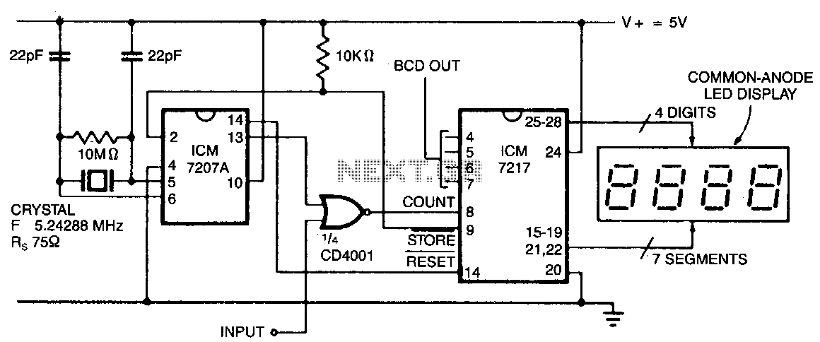
In this configuration, the display shows hertz directly. When pin 11 of the ICM7027 A is connected to V00, the gating time is set to 0.1 seconds, allowing the display to represent tens of hertz as the least significant...
Replacing the LC modulation circuit with an active filter allows for the elimination of large and costly inductance coils in frequency shift key control demodulators. This approach not only reduces the size of the circuit but also enhances the...
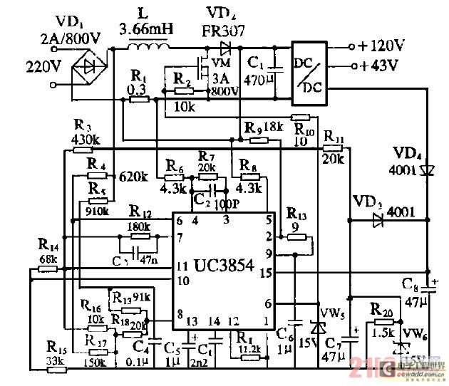
Improve the power factor (PF) to enhance energy conservation in electrical equipment. With advancements in electronic technology, high-frequency active power factor correction (PFC) technology has been increasingly applied across various power systems. The switching power supply of large-screen color...
A sine wave oscillator can be implemented using a Wien-Bridge oscillator, similar to the previous sine wave oscillator circuit; however, another method is now presented. The Wien-Bridge oscillator is a type of electronic oscillator that generates sine waves. It is...
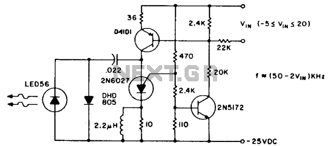
The pulse repetition rate is largely unaffected by temperature and power supply voltage, and it varies linearly with V1N, the modulating voltage. Effective information transfer was achieved at distances of 12 feet (~4m) in free air. A greater range...

The Wien bridge oscillator generates frequencies of 1 Hz and from 2 to 20 Hz in 2 Hz increments. The maximum output amplitude is 3 volts RMS or 8 volts peak-to-peak. A potentiometer and switch attenuator enable the output...