
Full Wave Rectifier Circuit with Averaging Filter
The described circuit employs operational amplifiers (op-amps) for signal processing, specifically to measure and convert AC voltage signals into a readable format. The design includes two main operational modes: averaging and absolute value generation, depending on the configuration of capacitors C1 and C2.
In the averaging mode, capacitor C2 plays a critical role by forming a low-pass filter with resistor R2. This configuration smooths the output signal, allowing the circuit to represent the average value of the input AC signal over time. The choice of resistor R2 and capacitor C2 values is essential; the time constant (τ = R2 * C2) must be selected to ensure that it is significantly greater than the period of the AC signal being measured, thus effectively filtering out high-frequency components and providing a stable average output.
In the absolute value mode, the removal of C1 ensures that the output reflects only the positive magnitude of the input signal, regardless of its polarity. This is particularly useful in applications where only the magnitude of the voltage is of interest, such as in power measurements or signal conditioning where negative voltages may not be applicable.
The circuit's design emphasizes the importance of precision in component selection. The operational amplifiers must be chosen for their ability to maintain accuracy in unity-gain configurations, which is critical for minimizing distortion and ensuring the fidelity of the output signal. Resistors R6 and R7 are strategically selected to counteract any potential errors introduced by input offset currents, which can lead to inaccuracies in the voltage readings.
Overall, the circuit combines efficiency and precision in measuring AC voltages, making it suitable for various applications in electronics, including instrumentation and control systems.This circuit is average reading use rms calibrated AC voltmeter. Deletion of C2 removes the averaging function and provides a precision full-wave rectifier, and deletion of C1 provides an absolute value generator. Circuit operation may be understood by following the signal path for negative and then for positive inputs.
For negative signals, the o utput of amplifier A1 is clamped to +0. 7V by D1 and disconnected from the summing point of A2 by D2. A2 then functions as a simple unity-gain inverter with input resistor, R1, and feedback resistor, R2, giving a positive going output. For positive inputs, A1 operates as a normal amplifier connected to the A2 summing point through resistor, R5.
Amplifier A1 then acts as a simple unity-gain inverter with input resistor, R3, and feedback resistor, R5. A1 gain accuracy is not affected by D2 since it is inside the feedback loop. Positive current enters the A2 summing point through resistor, R1, and negative current is drawn from the A2 summing point through resistor, R5.
Since the voltages across R1 and R5 are equal and opposite, and R5 is one-half the value of R1, the net input current at the A2 summing point is equal to and opposite from the current through R1 and amplifier A2 operates as a summing inverter with unity gain, again giving a positive output. Here is a schematic drawing : The circuit becomes an averaging filter when C2 is connected across R2.
Operation of A2 then is similar to the Simple Low Pass Filter previously described. The time constant R2C2 should be chosen to be much larger than the maximum period of the input voltage which is to be averaged. Capacitor C1 may be deleted if the circuit is to be used as an absolute value generator. When this is done, the circuit output will be the positive absolute value of the input voltage. The amplifiers chosen must be compensated for unity-gain operation and R6 and R7 must be chosen to minimize output errors due to input offset current.
🔗 External reference
Related Circuits
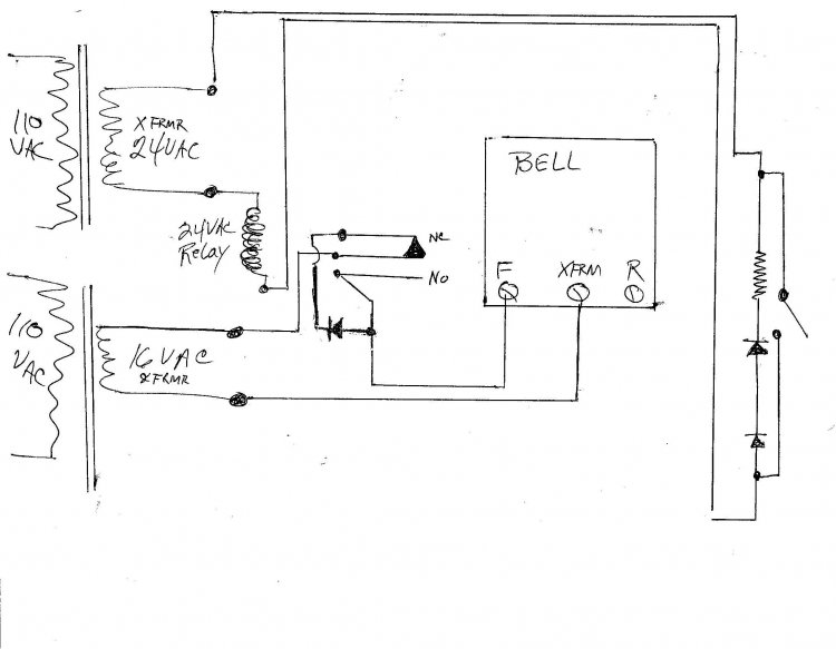
A new wired doorbell has been installed, specifically the Heath/Zenith Model #LE-65-B (Electronic). A new 16 Volt transformer was also added, along with a lighted pushbutton and a diode. Initially, all components functioned correctly, including the lighted pushbutton. However,...
Using an old moving coil instrument, it is easy to create a simple voltmeter that indicates the status of a telephone line at a glance. The circuit's high input impedance allows it to be permanently connected to the line,...
The metal detector circuit comprises an oscillator and a sound-light alarm circuit. The oscillator circuit includes an inductor (L), a capacitor (C1), a sensor switch integrated circuit (IC1) that integrates the oscillator, detector, comparator circuit, and peripheral components. The...
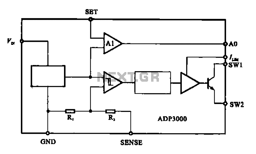
The ADP3000 is an integrated circuit featuring a block diagram that illustrates its internal structure as a high-frequency switching regulator. The ADP3000 integrated circuit is designed to provide efficient power management in various applications, particularly in systems requiring high-frequency switching...
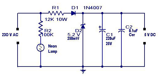
A simple transformerless power supply circuit with a diagram and schematics that provides a 5 volts DC output. This is a low-cost, low-current power supply circuit suitable for simple applications such as powering an LED. The transformerless power supply circuit...
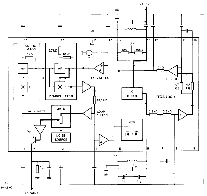
GENERAL DESCRIPTION The TDA7000 is a monolithic integrated circuit designed for mono FM portable radios or receivers, emphasizing minimal peripheral components to achieve compact dimensions and reduced costs. This integrated circuit features a Frequency-Locked-Loop (FLL) system with an intermediate...