
Function Generators
Function generators are essential tools in electronics, providing a means to simulate various signal conditions for testing and analysis. The ability to produce multiple waveforms simultaneously allows for complex testing scenarios where two or more signals interact. This is particularly useful in applications such as modulation testing, where one waveform modulates another, or in systems requiring synchronization between different signal paths. The phase-locking capability further enhances the functionality of these devices, enabling precise control over the timing of signal outputs, which is crucial in applications like digital communications and signal processing.
In practical applications, function generators are used in laboratories for experimentation, in educational settings for teaching purposes, and in various industries for testing and development of electronic devices. The versatility in waveform generation makes them suitable for a wide range of tasks, from basic signal generation to complex waveform shaping required in advanced electronic systems. The design of a function generator often includes user-friendly interfaces that allow for easy adjustment of parameters such as frequency, amplitude, and waveform type, ensuring that users can quickly configure the generator to meet their specific needs.A function generator is a signal source that has the capability of producing different types of waveforms as its output signal. The most common output waveforms are sine-waves, triangular waves, square waves, and sawtooth waves. The frequencies of such waveforms may be adjusted from a fraction of a hertz to several hundred kHz. Actually the fun ction generators are very versatile instruments as they are capable of producing a wide variety of waveforms and frequencies. In fact, each of the waveform they generate are particularly suitable for a different group of applications.
The uses of sinusoidal outputs and square-wave outputs have already been described in the earlier Arts. The triangular-wave and sawtooth wave outputs of function generators are commonly used for those applications which need a signal that increases (or reduces) at a specific linear rate.
They are also used in driving sweep oscillators in oscilloscopes and the X-axis of X-Y recorders. Many function generators are also capable of generating two different waveforms simultaneously (from different output terminals, of course). This can be a useful feature when two generated signals are required for particular application. For instance, by provid ing a square wave for linearity measurements in an audio-system, a simultaneous sawtooth output may be used to drive the horizontal deflection amplifier of an oscilloscope, providing a visual display of the measurement result.
For another example, a triangular-wave and a sine-wave of equal frequencies can be produced simultaneously. If the zero crossings of both the waves are made to occur at the same time, a linearly varying waveform is available which can be started at the point of zero phase of a sine-wave.
Another important feature of some function generators is their capability of phase-locking to an external signal source. One function generator may be used to phase lock a second function generator, and the two output signals can be displaced in phase by an adjustable amount.
In addition, one function generator may be phase locked to a harmonic of the sine-wave of another function generator. By adjustment of the phase and the amplitude of the harmonics, almost any waveform may be produced by the summation of the fundamental frequency generated by one function generator and the harmonic generated by the other function generator.
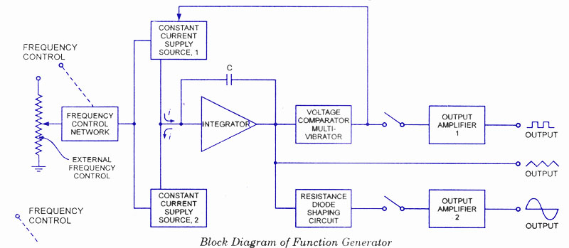
The function generator can also be phase locked to an accurate fre quency standard, and all its output waveforms will have the same frequency, stability, and accuracy as the standard. The block diagram of a function generator is given in figure. In this instrument the frequency is controlled by varying the magnitude of current that drives the integrator.
This instrument provides different types of waveforms (such as sinusoidal, triangular and square waves) as its output signal with a frequency range of 0. 01 Hz to 100 kHz. The frequency controlled voltage regulates two current supply sources. Current supply source 1 supplies constant current to the integrator whose output voltage rises linearly with time.
An increase or decrease in the current increases or reduces the slope of the output voltage and thus controls the frequency. The voltage comparator multivibrator changes state at a predetermined maximum level, of the integrator output voltage.
This change cuts-off the current supply from supply source 1 and switches to the supply source 2. The current supply source 2 supplies a reverse current to the integrator so that its output drops linearly with time. When the output attains a pre determined level, the voltage comparator again changes state and switches on to the current supply source.
The output of the integrator is a triangular wave whose frequency depends on the current supplied by the constant current supply sources. The comparator output provides a square wave of the same frequency as output. The resistance diode ne 🔗 External reference
Related Circuits
The XC6119 series is a highly precise, low power consumption voltage detector, manufactured using CMOS and laser trimming technologies. The device includes a built-in delay circuit. A release delay time can be set freely by connecting an external delay...
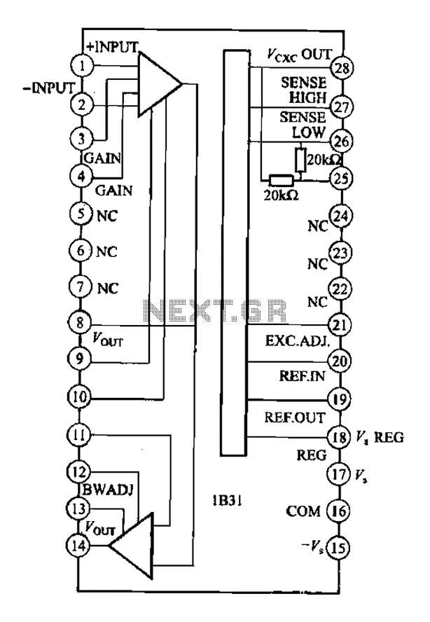
The Analog Devices 1831 is designed for strain gauge signal conditioning applications. It features an internal low drift input of 0.25V with a gain of 1000, exhibiting excellent linearity with a maximum deviation of 0.005%. The IC operates with...
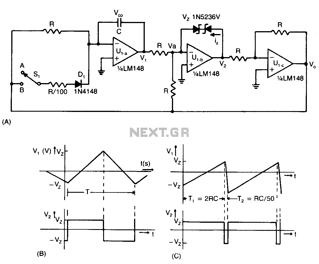
This low-cost operational amplifier circuit (A) generates four different functions with adjustable periods. For the components shown here, the period of the output waveforms is given by T = 4RC and T = 2RC. When switch SI is in...
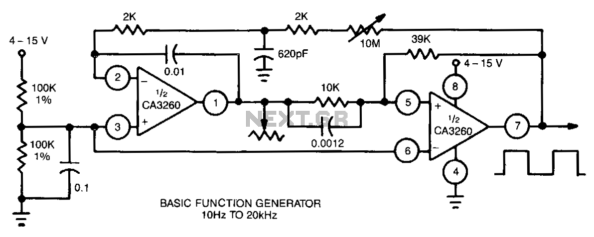
This function generator utilizes a CA3260 BiMOS operational amplifier to perform both integrator and switching functions. A 620-pF capacitor and a 2-kΩ resistor are employed to shape the feedback square wave, minimizing spikes. The device covers the full audio...
Conexant's CX24501 is a highly integrated back-end decoder IC solution that supports MPEG-2, H.264, and VC-1 formats. It is compliant with DIRECTV and DVB standards, making it suitable for high-definition digital television applications. This decoder can be utilized in...
This site contains complete schematics and code for a 68HC11 based frequency counter, square wave synthesizer, sine wave synthesizer, programmable filter, capacitance and inductance meter, with a digitalker speech synthesizer output. Project specifications are given below. The project outlined involves...
Warning: include(partials/cookie-banner.php): Failed to open stream: Permission denied in /var/www/html/nextgr/view-circuit.php on line 713
Warning: include(): Failed opening 'partials/cookie-banner.php' for inclusion (include_path='.:/usr/share/php') in /var/www/html/nextgr/view-circuit.php on line 713