
FYProject12
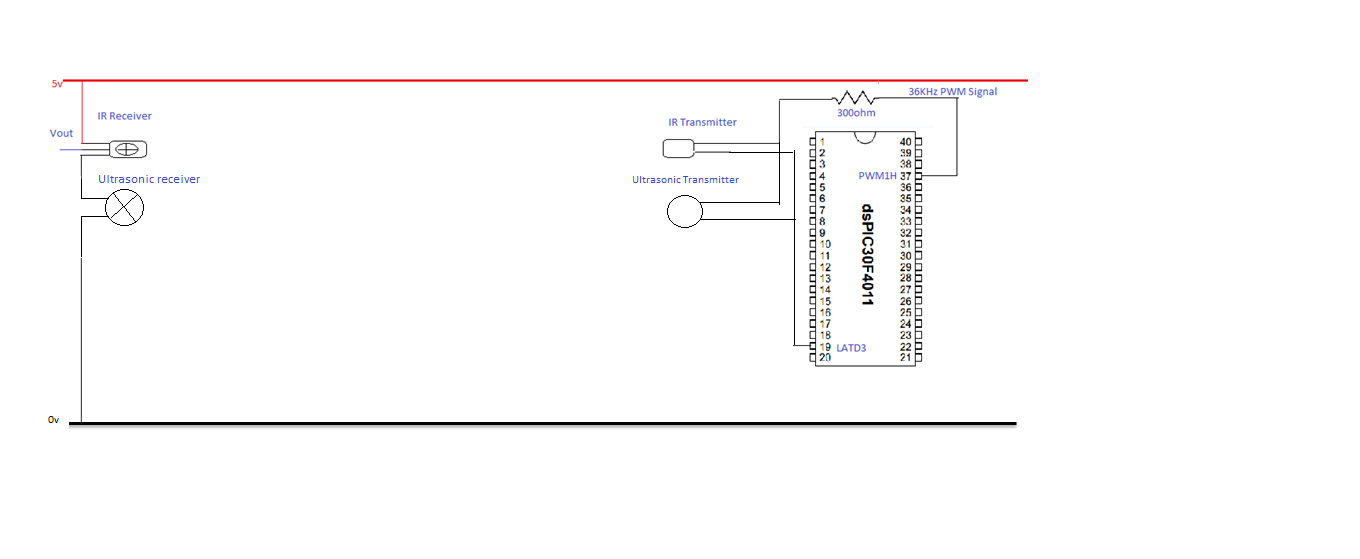
The objective of this experiment is to evaluate the range of the ultrasonic sensors (transmitter and receiver) utilized in this project. The sensor will be tested over a distance of 5 meters. The transmitter will be positioned directly facing the receiver at distances of 1m, 2m, 3m, 4m, and 5m. At each distance, the signal received from the ultrasonic receiver will be displayed on an oscilloscope, and the voltage will be recorded. The experiment shows that as the distance between the transmitter and receiver increases, the voltage output of the receiver decreases. When the receiver is moved further than 1m from the transmitter, the average voltage signal drops to 50mV or lower. The goal is for the ultrasonic receiver to output a higher voltage even at longer distances, with a target range of 1-2V being acceptable, while any voltage value above this would be considered ideal. The ultrasonic components used in this experiment operate at a maximum voltage of 20V, but the supply voltage is set at 5V provided by the DsPIC. To enhance the voltage levels at the ultrasonic receiver, a suggestion is made to utilize a MAX232 voltage driver. The MAX232 accepts a supply voltage of 5V and provides an output voltage of +/-10V. This +/-10V output could be utilized to power the ultrasonic transmitter, potentially resulting in an increase in the voltage output of the ultrasonic transceiver.
The experimental setup for testing the ultrasonic sensors involves a systematic approach to measure the effectiveness of the sensors over a specified range. The transmitter and receiver are aligned to ensure direct communication, minimizing potential signal loss due to misalignment. The oscilloscope serves as a critical tool for visualizing the received signals, allowing for real-time analysis of the voltage levels at varying distances.
In terms of circuit design, the ultrasonic transmitter typically consists of a piezoelectric element that generates ultrasonic waves when an alternating voltage is applied. The receiver, also a piezoelectric element, detects the reflected ultrasonic waves and converts them back into electrical signals. The voltage output from the receiver is influenced by distance, environmental factors, and the characteristics of the ultrasonic transducer.
To address the observed decrease in voltage output with distance, implementing a MAX232 voltage driver can significantly enhance performance. The MAX232 is a dual driver/receiver that is commonly used for converting TTL logic levels to RS-232 levels, but it can also be employed to boost the output voltage for the ultrasonic transmitter. By providing a higher voltage supply to the transmitter, the amplitude of the emitted ultrasonic waves can be increased, which in turn improves the likelihood of detection by the receiver at greater distances.
In conclusion, the experiment's findings highlight the importance of optimizing the voltage levels in ultrasonic sensor applications. By utilizing a MAX232 voltage driver, the overall performance of the ultrasonic transceiver can be improved, leading to better operational range and efficiency in various applications such as distance measurement, object detection, and automation systems.The objectives of this experiment is to test the range of the ultrasonic sensors(transmitter and receiver) being used in this project. The senor will be tested over the range of 5m. The Transmitter will be set up directly facing the receiver at distances of 1m 2m 3m 4m and 5m. At each distance the signal received from the ultrasonic receiver will be displayed on the oscilloscope and the voltage recorded. As can be seen from the experiment, as the distance between transmitter and receiver increases the voltage output of the receiver decreases. After the receiver is moved further away from the transmitter than 1m, the average voltage signal is 50mV and less.
It is desired that the ultrasonic receiver output a higher voltage than this even at long distances. A voltage of 1-2v would be acceptable while any voltage value higher than this would be almost ideal. The ultrasonic components used in this experiment operate at a max voltage of 20v, in this experiment the supply voltage is the 5v supplied by the DsPIC.
A possible suggestion to improve the voltage levels at the ultrasonic receiver would be to use a MAX232 voltage driver. The MAX232 receives a supply voltage of 5v and gives an output voltage of +/-10v. This +/-10v would be used to supply the ultrasonic transmitter which should result in a step up in the voltage output of the ultrasonic transceiver.
🔗 External reference