
Gain-Controlled Amplifier
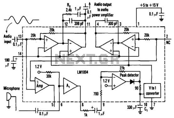
The described circuit utilizes the LM1894 integrated circuit, which is designed for automatic gain control (AGC) in audio applications. The primary function of this circuit is to ensure that audio output levels remain consistent despite variations in ambient noise levels.
In operation, the circuit begins with sound waves being captured by a microphone, which converts the acoustic signals into an electrical signal. This signal is then coupled to pin 6 of the LM1894 through a 0.1 µF capacitor. The capacitor serves to block any DC offset from the microphone, allowing only the AC audio signal to pass through. The LM1894 processes this audio input to determine the appropriate gain level needed based on the detected ambient noise.
The variable-gain amplifier (VGA) within the LM1894 adjusts the audio gain dynamically. When the environment is quiet, the gain is reduced, resulting in a lower audio output at pin 11. Conversely, in a noisy environment, the gain increases, amplifying the audio output to ensure it is audible. The amplified output is then taken from pin 11, which is also connected through another 0.1 µF capacitor. This output capacitor serves to filter out any DC component from the amplified signal, providing a clean audio output suitable for further processing or amplification.
The design of this circuit is particularly useful in applications where ambient noise levels can fluctuate significantly, such as in public address systems, hearing aids, or any audio device that requires adaptive volume control. This ensures optimal performance and user experience by maintaining audio clarity and consistency across varying environmental conditions. This single-chip circuit adjusts its audio gain according to the ambient noise picked up by the microphone. When operating in a quiet environment, the audio output is quiet, while a noisy environment results in a louder audio output. Audio to pin 13 is amplified by the variable-gain amplifier within the LM1894 IC. Audio from the microphone connected through 0.1-/iF capacitor to pin 6 controls the audio gain of the variable-gain amplifier.
The output appears on pin 11 and is taken off through an 0.1-/xF capacitor. 🔗 External reference
Related Circuits
The following circuit diagram represents a simplified application circuit of the TDA8932B/33(B) device when operated from an asymmetrical (single) supply. To streamline the design for an asymmetrical supply in a single-ended (SE) configuration, the TDA8932B/33(B) incorporates three integrated half-supply...
The tracing of the BASH amplifier circuit for the V. 2-400 has been documented through schematics that reflect the findings. Design defects have been identified, and improvements are being implemented. Evan Shultz dedicated considerable time to tracing the circuits...
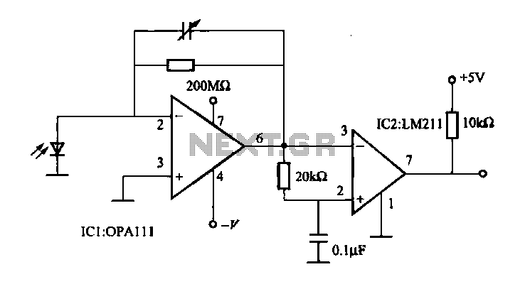
The OPA111 optical receiver amplifier features a feedback resistor of 200 MΩ, which is crucial due to the high gain of the amplifier. The OPA111 is designed to receive signals transmitted over optical fiber, specifically at a rate of...
The 10-meter 27MHz continuous wave (CW) radio amplifier is equipped with the VN66AF transistor produced by Siliconix, which offers several advantages: it is inexpensive, provides excellent dielectric insulation, and has high gain. The VN66AF is utilized as an RF...
Feedback - This is where part of the output signal is fedback to the input BUT 180° out-of-phase (i.e. partially cancels the input). If it were in-phase feedback then we would have an oscillator - which in this case...
Measure the voltage across the 1k resistor connected to the input stage and Vcc. The DC voltage should be approximately 2 volts, or 2 mA of current flowing through this resistor. For instance, if Vcc is at 24 volts,...