
Game-scoring Display ScreenCircuit
The game-scoring display circuit is designed to facilitate real-time scoring for games, allowing players to track their scores accurately. The circuit can be divided into four main functional blocks.
1. **Add/Subtract Scoring Input Circuit**: This section receives input signals that determine whether the score should be increased or decreased. Typically, this circuit may utilize push-button switches or other input devices that generate a high or low signal corresponding to scoring actions. The signals are processed to determine the direction of scoring—addition or subtraction.
2. **Add/Subtract Scoring Circuit**: This block processes the input from the scoring input circuit. It utilizes logic gates or an arithmetic logic unit (ALU) to perform the necessary calculations based on the input signals. The output from this circuit will represent the current score, which can be a positive or negative integer depending on the scoring actions taken.
3. **Counting-Decoding Display Circuit**: The output from the scoring circuit is then fed into a counting-decoding circuit, which translates the numerical score into a format suitable for display. This may involve the use of binary-coded decimal (BCD) encoders or similar components that convert the score into a format that can be displayed on a digital screen, such as seven-segment displays or LCDs. This circuit ensures that the score is visually represented in a clear and understandable manner.
4. **Reset Circuit**: To facilitate game resets, a reset circuit is included. This circuit allows the score to be cleared and set back to zero, preparing the display for a new game. The reset function can be triggered by a dedicated button or automatically at the start of a new game session.
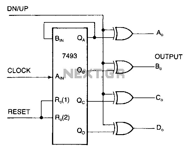
Overall, the game-scoring display screen circuit is essential for providing immediate feedback to players regarding their scores, enhancing the gaming experience through accurate and efficient score management. Each component of the circuit plays a crucial role in ensuring reliable operation and user interaction.Game-scoring display screen circuit diagram is shown as in the above picture. The circuit is composed of add/subtract scoring input circuit, add/subtract scoring circuit, counting - decoding display circuit and reset circuit.. 🔗 External reference
Related Circuits
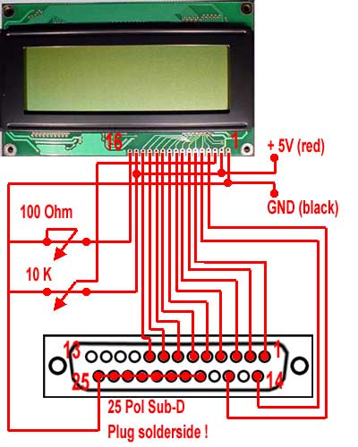
For the wiring of the display, the ribbon cable is first taken and soldered according to the circuit diagram on the 25-pin sub-D (parallel port) plug. The small circuit diagram illustrates the rear side, which is the solder side...
Running Message Display Circuit Diagram. This circuit is based on the CD401 IC. Features: Light emitting diodes are advantageous due to their smaller size. The Running Message Display Circuit utilizes the CD401 integrated circuit, which is a versatile component in...
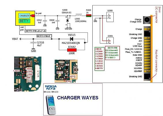
The display lights issue on the Nokia N73 can arise from various factors, such as a broken path in the display circuit or damage to the display driver, among others. This mobile repair guide offers pictures related to the...
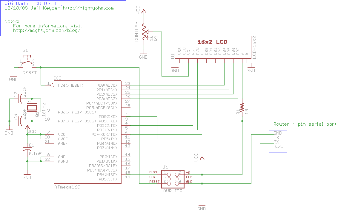
This is the seventh part of an ongoing series about building a low-cost, open-source streaming internet radio. If you have not already, check out the previous parts for some background about the project. In part six, UNIX-style shell commands...
The display interface utilizes the ICM7218A/B in conjunction with an 8048 family microcontroller. An 8-bit data bus (DBO/DB7-IDO/ID7) facilitates the transfer of control and data information to the 7218 display interface during successive WRITE pulses. The mode input pins...
It is very interesting and convenient to be able to control everything while sitting at your PC terminal. Here, a simple hardware circuit and software is used to interface a 7-segment based rolling display. The printer port of a...