
Gated 1Khz Oscillator (Normally On) Circuit
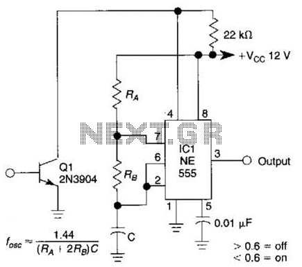
The gated 1-kHz oscillator circuit is designed to generate a square wave output at a frequency of 1 kHz. This oscillator is particularly notable for its press-to-turn-off operation, allowing for the circuit to be easily disabled by pressing a designated button or switch. This feature enhances user control over the oscillator's operation.
The oscillator typically employs a feedback mechanism involving a timing capacitor (C1) and resistors to set the frequency of oscillation. The output of the oscillator can be observed at pin 3, which serves as the primary output point where the square wave signal is available for further processing or driving other components in a circuit. The waveforms produced at this output can be analyzed for characteristics such as duty cycle, amplitude, and stability.
Capacitor C1 plays a crucial role in determining the timing characteristics of the oscillator. Its charge and discharge cycles, influenced by the resistor network, dictate the oscillation frequency. The output waveform at pin 3 can be utilized in various applications, including clock generation, signal modulation, and as a timing reference in digital circuits.
In summary, this gated 1-kHz oscillator circuit is a versatile component that provides essential timing functions with the added convenience of a user-friendly press-to-turn-off feature. The outputs are suitable for interfacing with other electronic systems, making it a valuable addition to any electronic design requiring precise timing control. This gated 1-kHz oscillator offers press-to-turn-off operation, A, and waveforms at the output of pin 3 and across CI, B. 🔗 External reference
Related Circuits
The following circuit diagram depicts a 100 Watt audio power amplifier, constructed using the LM3886 power amplifier chip. A single LM3886 IC can amplify audio power output up to 68W. In this circuit, two LM3886 chips are configured in...
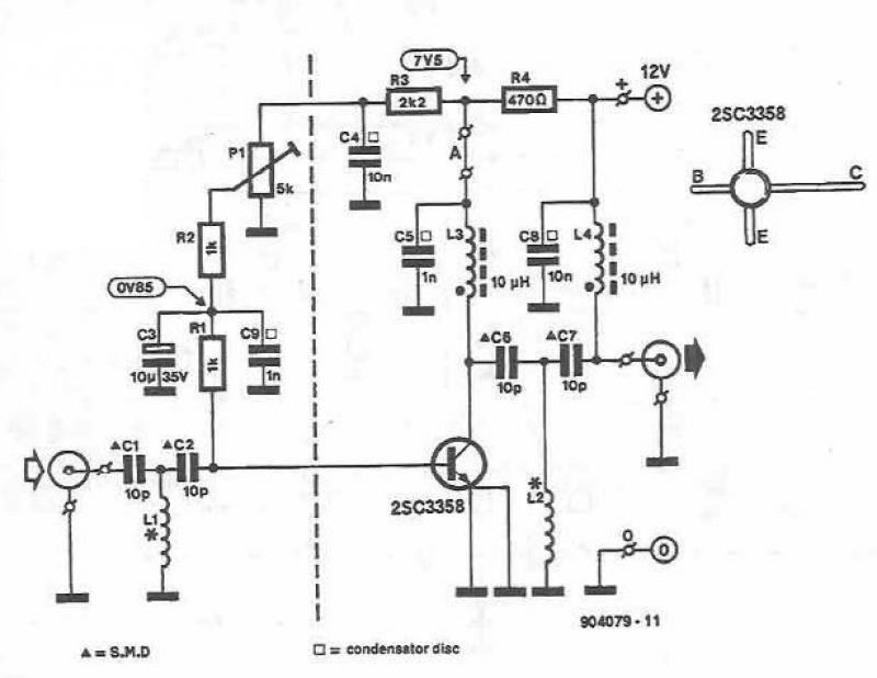
This UHF amplifier circuit project is beneficial for enhancing weak TV signals. The amplifier provides a gain of 10-15 dB within a frequency range of 400 to 850 MHz. To ensure optimal performance and reliability, the PCB tracks should...

This is a transistor tester integrated into a circuit or printed circuit board (PCB). It is utilized when a project does not function correctly, allowing for the testing of electronic components. The transistor tester is a crucial tool in electronic...
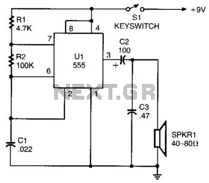
A 555 timer configured as an astable multivibrator is used in this circuit to generate an audio note. The capacitance value can be changed to vary the audio note as desired. The circuit utilizes a 555 timer IC, which...

Any NPN transistor can be used. The author used a 2N3904, but a 2N2222A should work just as well. A good, low noise transistor would be even better. Some radios only have three connections to their ferrite bar antenna:...
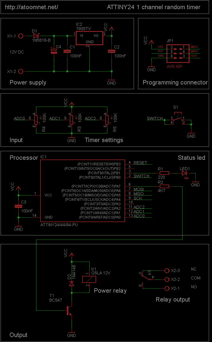
This random timer circuit is based on an Atmel ATTINY24 AVR driving one power relay. It can be used to switch on and off other circuits randomly. For instance, in a model railroad setup, this circuit can activate and...